Fire-Tube Boilers Multitubular Boiler Horizontal Many Small Fire Tubes Externally-Fired
shown and front
FIRE-TUBE BOILERS MULTITUBULAR BOILER: HORIZONTAL, MANY SMALL FIRE TUBES, EXTERNALLY-FIRED When engineers found that the internal flue was such an advantage (that is, it increased the heating surface), they soon added more tubes; as the number increased, the size diminished until they became of the size used at present. This is in brief the development of the multitubular boiler. This type of boiler has for many years been commonly used for stationary work and although other types possess advantages for certain conditions, it is still considered economical, reliable, easily handled, and safe if constructed of good material and operated with care and intelligence.
Figs. 11 to 14 are selected to illustrate this boiler. The boiler without the brick setting is shown in Fig. 11. It consists of a steel cylindrical shell and numerous small tubes extending from end to end. These tubes are 3 or 4 inches in diameter and are fastened to the two ends (called tube sheets) by expanding the tubes against the sheet and beading them over on the outside. The shell is made of steel plates 1/4 to 3/4-inch in thickness. At the front, the shell plates extend beyond the tube sheet and are cut away to allow the waste gases to enter the uptake. About onethird the volume of the boiler is occupied by the steam; the other two-thirds is filled with water and tubes. The water line is a little (from 4 to 8 inches) above the top row of tubes.

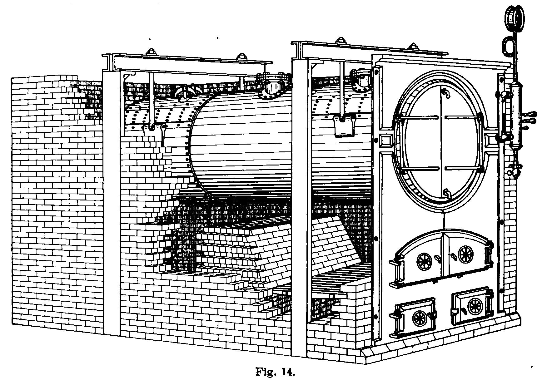
The flat ends are prevented from bulging by stays which may be of the form shown in Fig. 12 or they may be diagonal stays. The through stays are fastened to the tube, plates by means of nuts and washers as shown at S in Fig. 11, and also in Fig. 12. Below the water level, the end plate is stayed by the tubes. This type of boiler may be supported by brackets B riveted to the shell or by means of beams and columns, as shown in Fig. 14. The front bracket is often fixed in the side wall, but the rear bracket should be placed on rollers so that it can move on an iron plate. This will prevent the straining of the plates from expansion and contraction. A small space must be left between the rear tube sheet and the brick wall to allow for expansion.

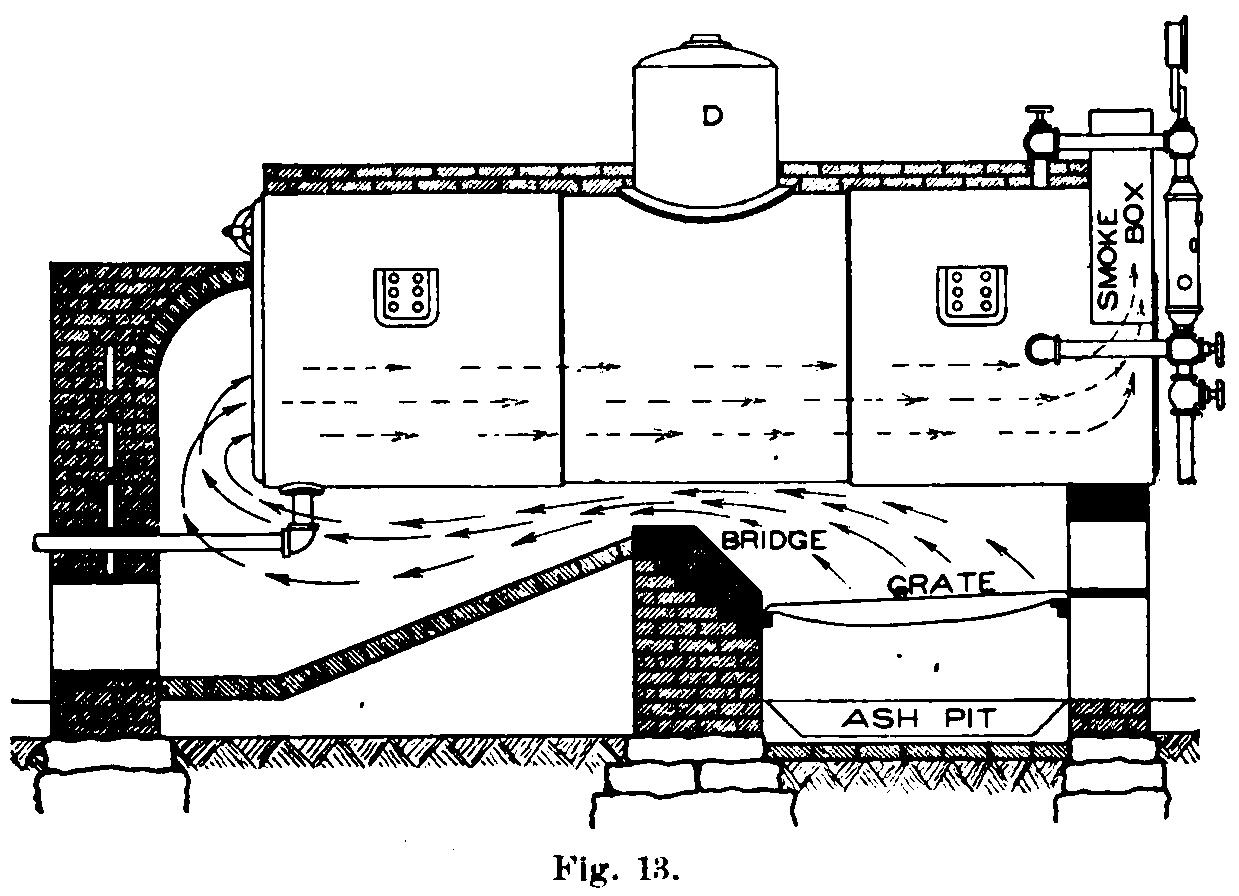
The boiler shown in Fig. 11 has two steam nozzles N. If the boiler has a dome (D Fig. 13) the steam nozzle is at or near the top of the dome The feed pipe may enter either at the front or at the rear. It frequently terminates in a perforated pipe below the
water line. The blow-off pipe is at the rear of the boiler as shown in Fig. 13, A valve, called the blow-off valve, regulates the flow and may be opened, when. there is low pressure in the boiler, to blow out sediment and detached scale. The boiler is usually set with a slight inclination toward the rear so that mud and detached scale may collect near the blow-off pipe.
In order that the boiler may be entered for cleaning or repairs, it is provided with manholes and handholes. Fig. 11 shows a manhole M at the top near the middle and a handhole near the bottom of the front tube sheet. Handholes may be put in wherever desired, but manholes can be located only where the arrangement of stays and tubes will permit the entrance of a man. Manholes and handholes are elliptical; the former being about 11 inches by 15 inches in size; while the latter are about 4 inches by 6 inches.
The heating surface is the surface in contact with the hot gases. In this type, the heating surface is made up of about half the shell, the tubes, and about two-thirds of the rear tube sheet.
In general, all the heating surface is below the water line.
The complete multitubular boiler is shown in its brick setting in Fig. 14, and a longitudinal section of the setting in Fig. 13.
The brick setting consists of brick laid in cement or mortar. The bridge and the portions of the furnace exposed to the fire are lined with firebrick. The bridge is built at the rear of the grate and forms a support for the grate bars; it also directs the flames upward. Thearrows show the direction of the flow of hot gases. The furnace is formed by the bridge, the side walls, and the lower part of the boiler front. The Ģ boiler front is usually of cast iron with the lower part lined with fire brick. The front has doors which lead to the furnace,-ashpit, and smoke box. The space below the grate is called the ashpit, and through its doors ashes are removed and a large portion of the air for combustion enters. Both the fire doors and ashpit doors have draft plates, or grids, to regulate the supply of air. The doors to the smoke box give access to the tubes for cleaning and repairs.