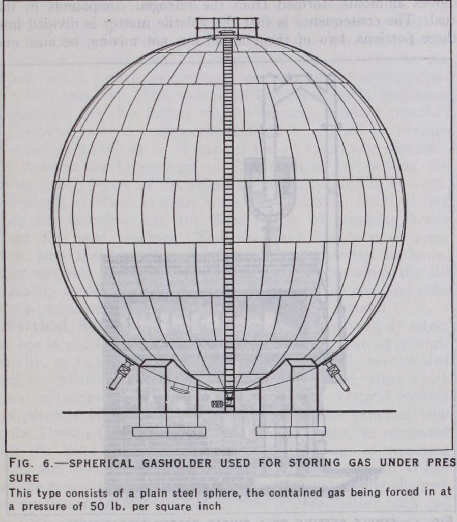
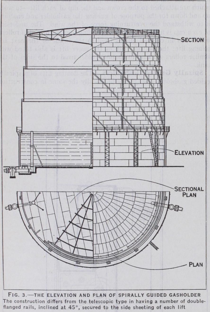
GASHOLDERS. As the manufacture of gas must be main tained at an approximately even rate throughout the 24 hours, while the rate of consumption varies considerably at the different hours of the day, it is necessary to provide storage for the gas produced during the periods of minimum demand, and also to provide against any temporary breakdown in the manufacturing plant. In the early days of the gas industry the vessel in which the gas was stored was known as a "gasometer," as this vessel had to serve the dual purpose of storing and measuring the amount of gas made. With the advent of the station meter in the year 182o for measuring the volume of gas, the name of "gasholder" was adopted, but even now in Great Britain journalists and others invariably use the technically obsolete word "gasometer." The capacity of the gasholder should be equal to at least 75% of the maximum daily output. There are now f our distinctive types of gasholders: (I) frame guided, (2) spirally guided, (3) dry or tankless, (4) spherical. The frame guided and spirally guided holders may have one or more lifts, the one lift type being known as a single lift holder, and the other as a telescopic gasholder, the latter type being generally adopted for economic reasons. The movable vessel in which the gas is stored is known as the floating gasholder. The steel structure which guides the floating holder as it ascends or descends is termed the guide framing, and is erected round the circumference of the steel or brick tank which contains the water for sealing the sides of the floating gasholder, thus preventing the escape of gas. Gas is admitted into the holder by means of an inlet pipe which passes through the bottom of the tank, and extends to a height of about 6 in. above the water level; another similar pipe is provided as an outlet for the gas to the district mains; both pipes being con trolled by slide valves.
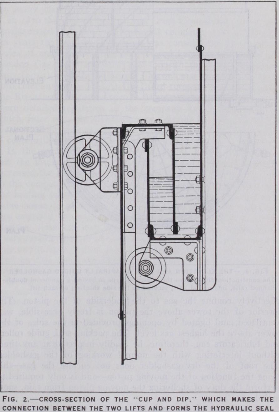
The telescopic form of holder (fig. i) consists of two or more lifts, which work or slide inside one another, much in the same way as an ordinary telescope. The inner or first lift is constructed to a certain diameter, according to the capacity required, and the diameter of each succeeding lift is increased by about 2 ft., whilst the depth of each lift would be constant, and equal to about one fifth the diameter. In order to secure a gas-tight joint between the lifts as they leave the tank, the bottom row of sheeting of the inner lift is prepared with a channel cup about 18 in. deep, whilst the top row of sheeting of the adjoining lift is fitted with an inverted channel cup, usually termed the "dip" (fig. 2) . As the inner lift rises out of the water in the tank, the channel cup engages with the dip, thus making a gas-tight water-sealed joint between the lifts. Each succeeding lift is fitted with a dip at the top, and a cup at the bottom, with the exception of the final or outer lift, which is provided with a dip at the top only, and a strong angle steel curb at the bottom. The crown of the holder is dome-shaped, and when at rest in the tank, is either supported by a trussed steel roof forming part of the inner lift, or upon a permanent steel or timber framing erected in the tank. The sheeting of the sides and crown of the holder is about in. thick, with the exception of the rows of sheets adjoining the cup and dip, and also the junction between the crown and sides of the inner lift, which are much thicker, in order to allow for extra wear and strain at these points. The tank may be constructed in brick, concrete or steel. Brick and concrete tanks are usually constructed by excavating the ground and building up the sides of the tank, so that the top of same finishes about 6 in. above the ordinary ground level. Water-tight ness is obtained by encasing the bottom and side walls of the tank in a layer of clay puddle, or by coating the inside surface of the tank walls with cement. Steel tanks are usually erected on a flat bed of concrete, laid at a foot or so below the normal ground level, the sides being formed of a number of tiers of steel plates varying in thickness to suit the pressure due to the depth of water in the tank. Steel tanks are much less costly than either brick or concrete tanks, and can be much more quickly erected.

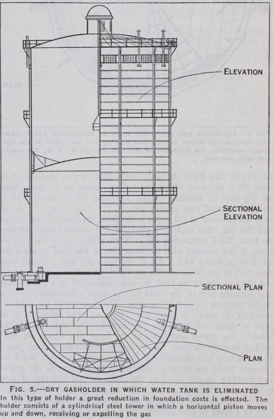
Another type of dry gasholder consists of a polygonal steel tower, with movable piston, similar in construction to that previously described, but in this design the periphery of the piston is maintained gas-tight by means of a light gas-tar of moderate viscosity, contained in an annulus formed on the outer edge of the piston. As this seal is not absolutely tar-tight, a small quantity of tar escapes and flows to the bottom of the cylinder, where it is collected in a series of chambers, and is pumped up again by a number of automatically controlled electric pumps, to the top of the tower.
See R. J. Milbourne, Gasholder Design and Construction.
(R. J. Mi.)