
GRAMOPHONE. An instrument for reproducing sound (Gr. ypep ua, letter, c/x.ovii, sound ), by transmitting to the air the mechanical vibrations of a stylus in contact with a sinuous groove in a moving record. In a wider sense the term might be applied to any instrument for the recording or subsequent reproduction of sound. As long ago as in 1857 Leon Scott had, by the invention of the "Phonautograph," provided means whereby visual records could be made of the vibrations of a diaphragm, but it was not until 1877 that the first "Talking Machine" was patented. Scott's Phonautograph consisted of a thin membrane, to which a delicate lever was attached. The membrane was stretched over the narrow end of a parabaloidal funnel, while the end of the lever was brought against the surface of a cylinder covered with paper on which soot had been deposited. The cylinder was fixed on a fine screw which moved horizontally when the cylinder was rotated. The marker thus described a spiral line on the blackened surface. When sounds were transmitted to the membrane and the cylinder was rotated the oscillations of the marker were recorded. Thus tracings of the vibrations were obtained (Comptes Rendus 53 p. The actual audible of recorded sound was first accomplished by T. A. Edison in 1876, the first patent specification being dated January 1877. In this instrument a spiral groove was cut on a brass drum fixed on a horizontal screw, so that when the drum was rotated it moved from right to left, as in the Phonautograph. The recorder consisted of a membrane of parchment or gold-beater's skin stretched over the end of a short brass cylinder about two inches in diameter. In the centre of the membrane there was a steel needle having a chisel-edge, and a stiff piece of spring steel was soldered to the needle near its point, the other end of the spring being clamped to the edge of the brass cylinder. The recorder was then so placed beside the large cylinder that the sharp edge of the needle ran in the middle of the spiral groove when the cylinder was rotated. The cylinder was covered with a sheet of tin-foil. During rotation of the cylinder, the sharp edge of the marker indented the tin-foil into the spiral groove, and when the membrane was caused to vibrate by sounds being thrown into the short cylinder by a funnel-shaped opening, the variations of pressure corresponding to each vibration caused the marker to make indentations of varying depth on the tin-foil in the bottom of the groove. These indentations corresponded to the sound-waves. To reproduce the sounds a second marker was caused to pass over the grooves of the cylinder, the marker being alternately elevated or depressed according to the nature of the indentations, and so transmitting to its membrane vibrations cor responding after a fashion to those which it was originally made to execute. These were then communicated to the air, so that the sound previously given to the "phonograph" (as Edison termed his invention) was reproduced in a crude but unmistakable manner.
Many improvements were attempted. In Edison's wax-cylinder phonograph, and in the "graphophone" of Graham Bell and C. S. Tainter, the sound record was produced by cutting instead of indenting an up-and-down line in the record material. Reproduc tions were made by an electro-deposition process similar to that used later for disc records. Machines employing cylindrical rec ords of the phonograph type enjoyed a wide popularity for many years. But the non-linear relation between the driving force and the amplitude of the cut, inherent in this method, led to the adop tion of means whereby the resistance of the record material to the motion of the cutting stylus was made more uniform, while the movement of the diaphragm in reproduction was positively con trolled by the record, and was not at times wholly dependent on the elasticity of the diaphragm, as in the phonograph. These im provements were introduced in 1887 by Emile Berliner. Berliner named his instrument the "gramophone." In the first drawing of his original patent specification, a cylindrical record, consisting of a strip of paper, coated with a layer of lamp-black and stretched round a drum, is used. Movement of the recording stylus is hori zontal and causes the removal of the lamp-black from the surface in a sinuous, spiral line. For purposes of reproduction he copied the record in a resisting material, either mechanically, or by en graving or etching, and this gave him a permanent record, con sisting of a wavy grooved line in a strip of copper, nickel or other material. To reproduce the sounds recorded, this strip was in turn stretched round a drum, the point of the stylus placed in the groove, and the drum rotated. Thus the first of Berliner's inven tions was virtually to provide means whereby Scott Phonauto graph records could be reproduced. In this connection it is to be noted that eleven years previously Charles Cros, a Frenchman, had deposited with the Academie des Sciences, Paris, a sealed packet containing a suggestion for doing this very same thing, though he cannot be said to have carried his ideas very far.

In the second or improved form of gramophone described in Berliner's patent specification, a flat record is used which, he says, offers advantage for copying purposes. A glass disc is covered with a semi-fluid coating of ink or paint, in which the stylus cuts a sinuous spiral running from the outer edge of the record to the centre, or vice versa. A turntable carries the record disc, and is rotated by any suitable means.
•Berliner's next step was to make a record in a solid material by direct etching. To this end he coated a disc or cylinder of zinc or glass with some substance which, while offering little resistance to the movements of the recording stylus, resisted the chemical action of acids. The coating he preferred consisted of beeswax dissolved in benzine. When the recording stylus had traced out its line on the record, and exposed the solid disc below, the latter was etched, and a permanent record produced. Copies could be made by the galvano-plastic process, by making a matrix, and impressing discs of hard rubber or the like. Owing to the undercutting of the protective coating by the acid a very rough record resulted, and it was not until the end of 1897 that the manufacture of disc records became a commercial success. The technique of record-making was now briefly as follows : Early Methods of Recording.—The players or singers were placed immediately before the mouth of a horn, which was used to concentrate the sound energy on the recording diaphragm. Singers were instructed to draw away from the horn at the moment of singing loud notes, in order to prevent "blasting." Orchestras were small; the players were crowded together and in some cases were given instruments of special construction to make up for the deficiencies in their number. The horn (or horns, for sometimes there were several) protruded through a screen, on the opposite side of which was the recording machine, carrying a disc-shaped blank of wax-like material, on which the recording stylus traced its spiral. From this disc, a solid metal negative or matrix was obtained by electro-deposition. Copies of the original record were then pressed from this matrix in a material which, while normally hard, became plastic under heat.
About this time a number of inventors began to turn their atten tion to the improvement of the reproducing machine. Successive stages of development are well illustrated by an interesting series of machines exhibited at the Science Museum of London, be ginning with an early Berliner disc machine with metal diaphragm sound-box and hand-drive. Mechanical governing was intro duced in 1896 and by the end of the century a clockwork machine, intended solely for reproduction, was made. This was provided with a celluloid diaphragm, but two years later mica was being used. By 1905, a type of sound-box had been evolved, the use of which persisted without radical change for twenty years. A mica diaphragm was held lightly at its edges by hollow rubber gaskets, the fulcrum of the lever connecting the centre of the diaphragm to the needle-point being formed by knife-edges, and its move ments controlled by delicate springs. It was found that better re production resulted from the use of larger horns, and when these became too heavy for their weight to be carried by the record they were removed from the sound-box and fixed to a bracket on the machine cabinet, the sound-box being connected to the small end of the horn by a piece of straight tubing known as a "tone-arm." This arrangement gave rise to increased distortion of the sound waves, until steps were taken to design the tone-arm as a tapering continuation of the horn. The appearance of the horn being looked upon by the public with disfavour, it became inverted and was placed inside the cabinet. From 1910 onwards this type of construction was generally preferred for domestic use.
The problems of electrical communication by line and radio had been intensively studied for many years by experts equipped with measuring instruments of a sensitivity and accuracy then unknown in acoustic research. Microphones (q.v.) and amplifiers (q.v.) of high quality were developed in connection with telephony and broadcasting, and were now available for the gramophone. It was therefore no longer necessary for the recording stylus to be actuated directly by the acoustic output of the performers them selves, grouped closely round the mouth of a horn. The performers could now be permitted to carry on their work in front of the microphone in commodious studios resembling nearly the normal conditions of musical performance or even in the actual concert-hall. The existence of amplifiers also made possible the use of quality-correcting devices which, even if it had been feasible to apply them in the acoustic recording process, would have unduly attenuated a motive energy already far too weak for many requirements. On the reproducing side, the proper function of a horn in communicating to the air the vibrations of a diaphragm had been investigated by A. G. Webster, who, in an important paper', outlined the properties of a logarithmic horn and also drew attention to the advantages to be derived by applying the concep tion of electrical impedance to acoustic and mechanical systems. The logarithmic horn was studied in detail by Hanna and Slepian, by P. B. Flanders, and by H. C. Harrison'. What remained to be done was to devise a systematic linkage between the micro phone and the recording stylus, and between the reproducing point and the mouth of the horn, of such a kind as take the fullest advantage of these new components.
knowledge of oscillation mechanics.
As previously mentioned, A. G. Webster had in 1919 already suggested the conception of mechanical and acoustic impedance as an aid to correct design. In 1926 J. P. Maxfield and H. C. Harrison published an account of their work in designing com plete recording and reproducing systems as analogues of the electric wave filters invented by G. A. Campbell in 1917'. Such filters are ideally composed of infinitely repeated similar sections, each section comprising one or more series and shunt elements. Structures of this type have in general one or more transmission bands of zero attenuation and one or more bands having infinite attenuation ; in gramophone technique single band-pass filters are of chief' interest, as will be seen later. Suppression of all but the first few sections of such an ideal structure does not seriously affect its properties so long as a suitable terminating resistance is applied. Without this termination the structure reduces to an assembly of n similar tuned circuits having collectively n different natural frequencies. Multi-resonant mechanical systems can, by the employment of damping and at the expense of efficiency, be designed to have excellent frequency characteristics, but the be haviour of such systems is best considered after that of a true mechanical band-pass filter has been thoroughly grasped.
Frequency Requirements of a Recording System.—The effi ciency with which a sound of any given pitch is radiated from a horn is independent of the intensity of the sound. This relation may be expressed in the form P where P is the power radiated, V the R.M.S. velocity of the air particles, and k a constant which may be defined as the radiation resistance of the horn at a particular frequency. When making records intended for mechanical reproduction, therefore, it is seen that, for correct balance, the recording tool should be made to move at constant maximum velocity at all frequencies. Under these conditions, for a given sound intensity, the amplitude of the cut is inversely proportional to the frequency. Whatever may be the degree of coarseness of the spiral record trace, therefore, there must bt some limit of frequency below which it is im possible to maintain a constant velocity without encroaching on the adjacent groove. Also, an upper frequency limit is imposed by the physical dimensions of the reproducing point, which is unable to follow the grooves when, at very high frequencies, their radius of curvature becomes extremely small. Maxfield and Harri son considered this matter and adopted a frequency characteristic of the uniform velocity type between the frequencies of 200 and about 4,00o cycles per second. Below 200 the system was modi fied to operate at approximately constant amplitude and above 4,000 at approximately constant acceleration. In this manner they were able to extend the range of frequencies recorded to 3o and to io,000 cycles, with some falling off towards these two opposite extremes.
Force (dynes) Electromotive Force (volts) Velocity (cm/sec) Current (amperes) Displacement (cm) Charge (coulombs) Impedance (dyne sec/cm) Impedance (ohms) Resistance (dyne sec/cm) Resistance (ohms) (or mechanical ohms) Reactance (dyne sec/cm) Reactance (ohms) (or mechanical ohms) Mass (gms) Inductance (henries) Compliance (cm/dyne) Capacity (farads) In deriving the equivalent circuit of any mechanical device, a compliance between two consecutive moving members is repre sented by a shunt capacity, and between a moving member and a rigid support by a series capacity. By proportioning the parts of a mechanical system it can be made to behave as an equivalent electrical network, and hence the peculiar properties of electrical filter circuits can be simulated.
'See bibliography.
The matter may be put somewhat differently as follows. In the older recording and reproducing systems there were numerous abrupt changes in the nature of the path along which the vibra tions were conducted from the mouth of the recording horn to the record and back again to the listener. This had the effect of introducing numerous resonances and greatly limited the range of musical tones which could be covered. By properly proportion ing the parts of each system, Maxfield and Harrison were able to smooth out these irregularities, with the result that the musical compass of the gramophone, and its fidelity to the original sounds within that compass, were greatly increased.
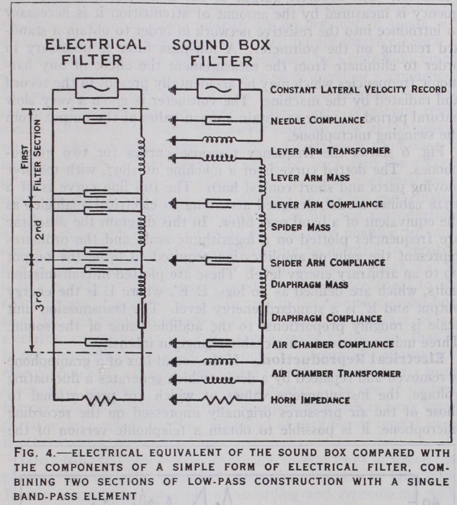
Maxfield-Harrison Gramophone.—The analogy between the mechanical and electrical filter is more perfectly shown in the reproducing equipment. The principle of "matched impedance" is of fundamental importance in the design of machines for mechanical reproduction, for here there are no amplifiers to make good the losses incurred in suppressing resonances. In applying the principle it was necessary to take into consideration the behaviour of an air-chamber behind the diaphragm and to determine its equivalent electrical elements before formulating the design. Fig. 3 shows a section of the Maxfield-Harrison sound box. Superimposed on each component the equivalent electrical component is shown, while in fig. 4 the mechanical elements are arranged diagrammatically for comparison with a simple form of electrical filter, combining two sections of low pass construction with a single band-pass element. As the series (diaphragm) compliance is so large that the low frequency cut-off which it causes lies well below that created by the horn, an inappreciable error is introduced in using for design purposes formulae of low pass filters. In an ordinary electrical filter, any section through the centre of the series impedances divides the filter into two parts, the impedances of which, looking forward and backward from the line of section, are matched. In this sound box two transformers are used, the needle arm with its lever action and the ratio of the areas of diaphragm to horn opening. Each of these steps up the velocity and hence in usual nomenclature would be described as a step-down transformer. The matching of impe dances by equivalent transformers is one of the chief points in the design of this sound box. In fig. 4 the record is to be regarded as the approximate equivalent of a constant current electrical generator, whose impedance is infinite. That this is not strictly true is evident from the fact that some record wear still occurs, but in spite of the increased amplitude of cut in records made by the electrical processes, less wear occurs with this type of sound box than with the earlier records and instruments.

The two formulae on which the design is based are as follows : where f e = the cut-off frequency of a transmission system in cycles per second; C = the shunt compliance per section in cen timetres per dynes; M = the series mass per section in grams; = the value of the characteristic impedance over the greater part of the band range.
It was found possible to make a satisfactory diaphragm of effective area 13 sq.cm. with a mass of o.186 grams; this value was theref ore taken for M. The cut-off frequency was chosen as 5,000, a compromise between the highest frequency occurring in the record and the increase in surface-noise when the cut-off fre quency is raised. Using these arbitrary values for two of the vari ables, equation (3) above shows that the values of all the equal shunt compliances and series masses in fig. 4 are determined ; while by substituting these values in equation (2) the characteristic im pedance of the system can be computed. For this particular design it is 2,92o mechanical ohms. Maxfield and Harrison made experiments from which it was calculated that for the reproduc tion to be sufficiently loud the radiation resistance of the entire system (i.e., the impedance as viewed from the record) should be approximately 4,50o mechanical ohms. A lever-arm trans former ratio of Z:sao was therefore incorporated to produce the necessary resistance.
The terminating resistance of the filter is provided by the horn, which is of the logarithmic type. There are two fundamental constants of such a horn. The first is the area of the large end and the second is the rate of taper. The area of the mouth de termines the lowest frequency which is radiated satisfactorily. The energy of the frequencies below this is largely reflected if it is permitted to reach the mouth. From the equations given by Webster it can be shown that all logarithmic horns have a low frequency cut-off which is determined by the rate of taper. It is, therefore, possible to build a horn in which the lowest fre quencies are prevented from reaching the mouth and so under going reflection, while all frequencies above the cut-off value are radiated. Such a horn will have no marked fundamental reso nance and will behave substantially as a pure acoustic resistance as required by the theory. Since the characteristics of the horn are determined by the area of its mouth and by its rate of taper, the length of the horn is determined by the area of the small end. This in turn is determined by the mechanical impedance and effective area of the system which it is terminating. It is seen, therefore, that the length of the horn should not be con sidered as a fundamental constant. Where it has been necessary to make a folded horn, difficulties have been encountered in settling the proper shape that this should take in order that its performance may approximate to that of a straight exponential horn. In practice a number of assumptions have been made which although not rigorously correct, have permitted the construction of compact horns having approximately the same properties as a straight logarithmic horn.
The output from the microphone or microphones is in most cases passed through a series of distortionless amplifying stages direct to the recorder, which is provided with a V-shaped cutting tool. The record blank is a tablet of a soapy wax, carried on a horizontal table which is rotated with uniform angular velocity by a weight-driven motor. As the table rotates it also travels laterally at a uniform speed, being carried on a revolving threaded spindle. The cutting point is lowered so as to enter the surface of the blank to a depth of a few mils, and as the machine runs it cuts a fine spiral groove of uniform depth, running from the cir cumference of the blank to within 2 or 3 inches of the centre. The lateral travel of the turntable is such that a record having about i oo grooves to the inch is made.
The record so prepared is dusted with graphite to make it electrically conductive, and is then slowly rotated in a copper plating bath. A homogeneous deposit of copper having thus been grown, it was at one time usual to take "dubs" or impresses in wax from the resulting negative. From this in turn one or more working matrices were made, from which the records were pressed. More recently, however, it has become standard practice to grow a whole series of negatives upon the original record, thereby obviating any necessity for a second wax impression.
Two classes of materials are used in the manufacture of the common breakable type of record, viz.,—resins and gums (of which the principal example is shellac) ; and various mineral fillers, which are used to lower the cost of production and to give increased resistance. From this material, records are pressed from the matrices in steam-heated hydraulic presses.
Flexible records, composed principally of celluloid, are also made. They are exceptionally free from surface noise but have hitherto proved inferior to wax in wear-resisting qualities.
Moreover, they cannot at once be determined by static measure ments alone. It is necessary to have some means for measuring the mechanical impedance of the parts in the degrees of freedom in which it is desired that they shall operate, as well as in those directions in which they should not be permitted to vibrate.
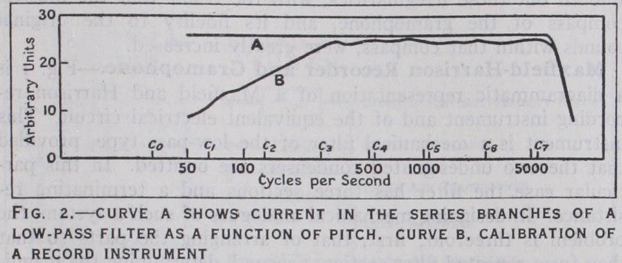
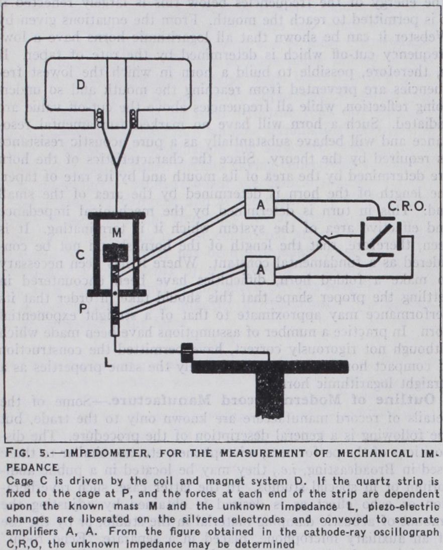
Fig. S shows diagrammatically a method of making such meas urements. A known mass M is attached to one end of a quartz strip, the other end of which is fixed to the driving point of the impedance L under examination. The strip is rigidly fastened at its centre P to a cage C which can be driven at any desired frequency by an electromagnetic coil and magnet system D. Near each end of the strip the two faces are silvered and connected through an amplifier A to one pair of plates of a cathode-ray oscillograph (see INSTRUMENTS, ELECTRICAL). The natural fre quency of the strip being made high in comparison with the fre quencies of operation, the piezo-electric effect (see ELECTRICITY) liberates on the electrodes at each end instantaneous charges whose magnitudes are proportional to those of the mechanical forces set up by the known mass and the unknown impedance respectively. The cathode beam is acted upon by these two forces at right angles to each other. From the resultant figure it is therefore possible to determine the relative phase and magnitude of the force exerted by the impedance under measurement. For example, if the impedance is purely reactive a straight line figure is pro duced; if resistive, the combination of forces due to the mass and to this resistance will give rise to an elliptical figure. The instru ment, which is termed an "Impedometer," is likely to be of value in the further practical applications of Maxfield and Harrison's ideas, especially in the search for suitable non-reactive mechanical resistances. A method which is used for obtaining the curve of response of a gramophone is as follows:— A number of records are made on a constant-velocity basis, of pure tones of given intensity. These are played on the machine under test, which is placed in a special room with heavy acoustic damping. The sound from the machine is picked up by a cali brated microphone which is swung from side to side during the test in order to nullify any effects due to standing waves in the room. The microphone is connected to an amplifier of which the performance is known, and the output from this is taken through a low-pass filter and a variable resistive network to a thermionic voltmeter. The acoustic output of the gramophone at any fre quency is measured by the amount of attenuation it is necessary to introduce into the resistive network in order to obtain a stand ard reading on the voltmeter. A low-pass filter is necessary in order to eliminate from the measurement the effect of any har monic frequencies which may be accidentally present in the record and radiated by the machine. The voltmeter is given a very slow natural period in order to obtain a mean value of the output from the swinging microphone.
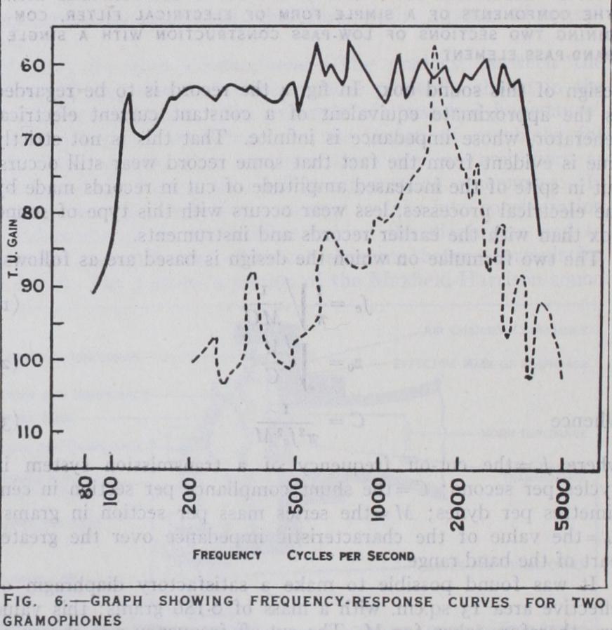
Fig. 6 shows the frequency response curves for two gramo phones. The dotted curve is of a machine of 1897, with massive moving parts and short conical horn. The full line curve is of a 1928 cabinet model, designed according to electrical analogies as the equivalent of a band pass filter. In this diagram the abscissae are frequencies plotted on a logarithmic scale and the ordinates represent the gain or amplification required to bring the output up to an arbitrary energy level. These are plotted in transmission units, which are defined as to E/E', where E is the energy output and E' is a standard energy level. The transmission unit scale is roughly proportional to the audible value of the sound. Three units represent a noticeable change in intensity.
A variety of pick-up devices have been utilised, but whether they comprise a moving-iron or a moving-coil system, an electro static arrangement or a piezo-electric crystal, there is in every case a reactive load due to the mass and compliance of the moving parts, so that it is generally necessary to apply some form of damping.
The lateral forces which act on the needle during reproduction (apart from that which urges it towards the centre of the record) are, first, a steady force, due to the fact that a line passing through the needle-point and the axis of rotation of the tone-arm cannot be exactly tangential to the record groove ; and second, a force due to the vibratory motion of the needle-point. The first of these can easily be kept within reasonable limits by careful design. The second may be regarded as the mechanical equivalent of an alternating voltage applied to a network—i.e., there can be any phase-relation with the current, which is here analogous to velocity. If the force and velocity are 90 deg. out of phase, no useful work is done, and the load is then purely reactive. Such a load would be furnished in electrical parlance by a pure inductance or pure capacity; mechanically, by a pure mass or compliance. In the older gramophones the load on the needle-point was ex tremely destructive to the record. There were numerous reso nances, and the load, which was purely resistive only at the peaks, was elsewhere almost wholly reactive. Under such conditions a large proportion of the energy is reflected back into the record groove with a difference of phase which in some cases may even result in the needle leaving the grooves altogether and cutting across them, with disastrous effects on the life and reproduction of the record. It is, as a matter of fact, only possible to con struct a mechanical system which shall not be harmful to records if it is substantially resistive over a wide frequency range, i.e., if it is a network correctly terminated by a resistance equal to its characteristic impedance. We have seen in the case of a sound-box that this resistance is provided by the horn. In the case of an electrical reproducer a difficulty arises owing to the fact that it is not required to do work, but only to generate variations of electric potential. It has been stated that the provision of a pure mechanical resistance is not a simple matter. The use of rubber, for example, introduces a reactive component which is large com pared with its resistance, and may lead to very heavy record wear if other compliances are added.
A second method of increasing the playing time, which could be combined with the above, consists in cutting the record with uni form amplitude instead of with uniform velocity, and correcting for the error by a suitable reproducing system. In the case of electrical reproduction this can easily be arranged; moreover it is permissible to reduce the amplitude down to any point where the ratio of surface noise to music is still reasonably small. In this way a much larger number of grooves may be included in the record. But records so made would be unsuitable for use with mechanical instruments of the type described in this article.