
CONDUCTION OF HEAT IN SOLIDS 3o. The transference of heat in the interior of a solid body formed one of the earliest subjects of mathematical and experi mental treatment in the theory of heat. The law assumed by Fourier was of the simplest possible type, but the mathematical application, except in the simplest cases, was so difficult as to require the development of a new mathematical method. Fourier succeeded in showing how, by his method of analysis, the solu tion of any given problem with regard to the flow of heat by conduction in any material could be obtained in terms of a physical constant, the thermal conductivity of the material, and that the results obtained by experiment agreed in a quali tative manner with those predicted by his theory. But the experi mental determination of the actual values of these constants presented formidable difficulties which were not surmounted till a later date.
The law of conduction, which forms the basis of the mathe matical theory, although seldom explicitly stated as an experi mental law, should really be regarded in this light, and may be briefly worded as follows : "The rate of transmission of heat by conduction is proportional to the temperature gradient." The rate of transmission of heat is here understood to mean the quantity of heat transferred in unit time through unit area of cross-section of the substance, the unit area being taken perpendicular to the lines of flow. It is clear that the quantity transferred in any case must be jointly proportional to the area and the time. The "gra dient of temperature" is the fall of temperature in degrees per unit length along the lines of flow.
The thermal conductivity of the substance is the constant ratio of the rate of transmission to the temperature gradient. To take the simple case of the "wall" or flat plate considered by Fourier for the definition of thermal conductivity, suppose that a quantity of heat Q passes per second through an area A of a plate of conductivity k and thickness x, the sides of which are constantly maintained at temperatures and The rate of transmission of heat is Q/A, and the temperature gradient, sup posed uniform, is so that the law of conduction leads at once to the equation (5) This relation applies accurately to the case of the steady flow of heat in parallel straight lines through a homogeneous and isotropic solid, the isothermal surfaces, or surfaces of equal temperature, being planes perpendicular to the lines of flow. If the flow is steady, and the temperature of each point of the body invariable, the rate of transmission must be everywhere the same. One of the simplest illustrations of the rectilinear flow of heat is the steady outflow through the upper strata of the earth's crust, which may be considered practically plane in this connection. This out flow of heat necessitates a rise of temperature with increase of depth. The corresponding gradient is of the order of I ° C in i oof t., but varies inversely with the conductivity of the strata at different depths.
A different type of problem is presented in those cases in which the temperature at each point varies with the time, as is the case near the surface of the soil with variations in the external condi tions between day and night or summer and winter. The flow of heat may still be linear if the horizontal layers of the soil are of uniform composition, but the quantity flowing through each layer is no longer the same. Part of the heat is used up in changing the temperature of the successive layers. In this case it is gen erally more convenient to consider as unit of heat the thermal capacity c of unit volume, or that quantity which would produce a rise of one degree of temperature in unit volume of the soil or substance considered. If Q is expressed in terms of this unit in equation (5) , it is necessary to divide by c, or to replace k on the right-hand side by the ratio k/c. This ratio determines the rate of diffusion of temperature, and is called the thermometric con ductivity or, more shortly, the diffusivity. The velocity of propa gation of temperature waves will be the same under similar con ditions in two substances which possess the same diffusivity, although they may differ in conductivity.
31. Variable-flow Methods.—In these methods the flow of heat is deduced from observations of the rate of change of tem perature with time in a body exposed to known external or boundary conditions. No calorimetric observations are required, but the results are obtained in terms of the thermal capacity of unit volume c, and the measurements give the diffusivity k/c, instead of the calorimetric conductivity k. Since both k and c are generally variable with the temperature, and the mode of variation of either is often unknown, the results of these methods are gen erally less certain with regard to the actual flow of heat. As in the case of steady-flow methods, by far the simplest example to con sider is that of the linear flow of heat in an infinite solid, which is most nearly realized in nature in the propagation of tempera ture waves in the surface of the soil. One of the best methods of studying the flow of heat in this case is to draw a series of curves showing the variations of temperature with depth in the soil for a series of consecutive days. The curves given in fig. 6 were obtained from the readings of a number of platinum thermometers buried in undisturbed soil in horizontal positions at M`Gill College, Montreal.
The method of deducing the diffusivity from these curves is as follows :—The total quantity of heat absorbed by the soil per unit area of surface between any two dates, and any two depths, x' and x", is equal to c times the area included between the corresponding curves. This can be measured graphically without any knowledge of the law of variation of the surface temperature, or of the laws of propagation of heat waves. The quantity of heat absorbed by the stratum (x' x") in the interval considered can also be expressed in terms of calorimetric conductivity k. The heat transmitted through the plane x is equal per unit area of surface to the product of k by the mean temperature gradient (dt/dx) and the interval of time in secs. The mean temperature gradient is found by plotting the curves for each day from the daily observations. The heat absorbed is the difference of the quantities transmitted through the bounding planes of the stratum. We thus obtain the simple equation k' (dt'/dx') —k"(dt"/dx") = c (area between curves)/time in sec., (6) by means of which the average value of the diffusivity k/c can be found for any convenient interval of time, at different seasons of the year, in different states of the soil.

For the particular soil in question it was found that the dif fusivity varied enormously with the degree of moisture, falling as low as •ooio C.G.S. in the winter for the surface layers, which be came extremely dry under the protection of the frozen ice and snow from December to March, but rising to an average of .006o to •0070 in the spring and autumn. The greater part of the diffu sion of heat was certainly due to the percolation of water. On some occasions, owing to the sudden melting of a surface layer of ice and snow, a large quantity of cold water, percolating rapidly, gave for a short time values of the diffusivity as high as .030o. Excluding these exceptional cases, however, the variations of the diffusivity appeared to follow the variations of the seasons with considerable regularity in successive years. The presence of water in the soil always increased the value of k/c, and as it necessarily increased c, the increase of k must have been greater than that of k/c.
32. Periodic Flow of Heat.—The foregoing method is per fectly general, and can be applied in any case in which the requi site observations can be taken. A case of special interest and importance is that in which the flow is periodic. The general characteristics of such a flow are illustrated in fig. 7, showing the propagation of temperature waves due to diurnal variations in the temperature of the surface. The daily range of temperature of the air and of the surface of the soil was about 20° F. On a sunny day, the temperature reached a maximum about 2 P.M. and a min imum about 5 A.M. As the waves were propagated downwards through the soil the amplitude rapidly diminished, so that at a depth of only 4in. it was already reduced to about 6° F, and to less than at loin. At the same time, the epoch of maximum or minimum was retarded, about 4 hours at 4in., and nearly i 2 hours at loin., where the maximum temperature was reached between I and 2 A.M. The form of the wave was also changed. At 4in. the rise was steeper than the fall, at loin. the reverse was the case. This is due to the fact that the components of shorter period are more rapidly propagated. For instance, the velocity of propaga tion of a wave having a period of a day is nearly twenty times as great as that of a wave with a period of one year; but on the other hand the penetration of the diurnal wave is nearly 20 times less, and the shorter waves die out more rapidly.
33. Laboratory Methods.—Measurements of thermal conduc tivity present peculiar difficulties on account of the variety of quantities to be observed, the slowness of the process of con duction, the impossibility of isolating a quantity of heat, and the difficulty of exactly realizing the theoretical conditions of the problem. The following are some of the special cases which have been utilized experimentally :— The "wall" or plate method endeavours to realize the conditions of equation (5), namely, uniform rectilinear flow. Theoretically this requires an infinite plate, or a perfect heat insulator, so that the lateral flow can be prevented or rendered negligible. This con dition can generally be satisfied with sufficient approximation with plates of reasonable dimensions. To find the conductivity, it is necessary to measure all the quantities which occur in equation (5) to a similar order of accuracy. The measurement of the temperature gradient in the plate generally presents the greatest difficulties. If the plate is thin, it is necessary to measure the thickness with great care, and it is necessary to assume that the temperatures of the surfaces are the same as those of the media with which they are in contact, since there is no room to insert thermometers in the plate itself. This assumption does not present serious errors in the case of bad conductors, such as glass or wood, but has given rise to large mistakes in the case of metals. The conductivities of thin slices of crystals have been measured by C. H. Lees (Phil. Trans., 1892) by pressing them between plane amalgamated surfaces of metal. This gives very good contact, and the conductivity of the metal being many times that of the crystal, the temperature of the surface is determinate.
Fig. 8 illustrates a modern example of the plate method, and shows how nearly the theoretical conditions can be realized with the aid of thermocouples and electric heating. To make the con ditions of heat-flow and heat-loss symmetrical, it is desirable to employ a pair of similar plates of the material to be tested, which in this case consist of quartzite of comparatively high conduc tivity, 15cm. square and 4cm. thick. The plates specimens are mounted on either side of an electric heater constructed of a pair of nichrome-asbestos mats of loo ohms each, separated by a pad of asbestos paper, and sandwiched between a pair of gunmetal plates, from which they are insulated by thin sheets of cabinet mica. Thus the heat generated by the electric current is evenly distributed in both directions over the surfaces of the specimens and is fully utilized for maintaining the heat-flow. The outer sur faces of the specimens are cooled by a pair of gunmetal plates, channelled for water circulation, and provided with a steady flow of cooling water at a constant temperature. When the electric current is turned on, a steady flow of heat through the specimens is rapidly established, and is readily determined by observing the volts on the heating mats. Thus with 7o volts on each mat, the total flow through each specimen is 49 watts, equivalent to 0.0522 gm. cal. per sq. cm. per sec. for the value of Q/A in equation (5) .
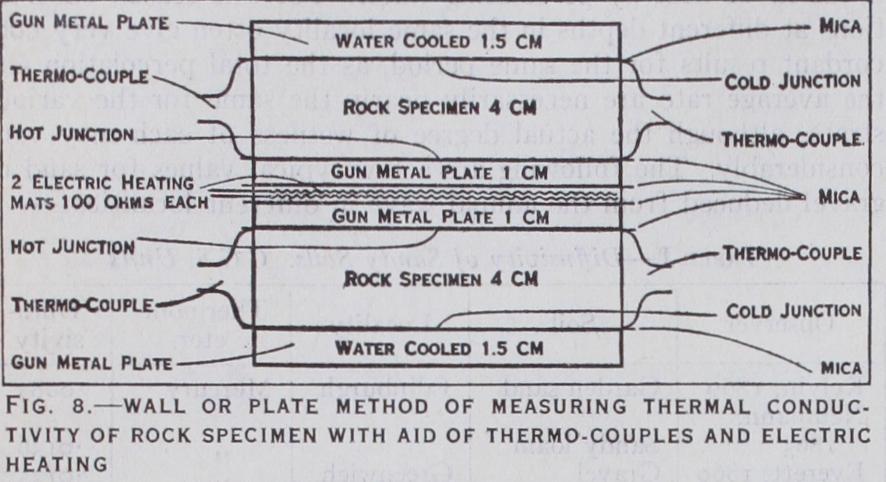
The temperature difference between the hot and cold surfaces of each specimen is measured by a copper-constantan thermo couple with its junctions at the centre of each surface. The wires are rolled to a thinness of 0•02mm. and are in direct contact with the surfaces of the rock specimens, being insulated from the gun metal plates by thin sheets of cabinet mica. With 7o volts on each heating mat, the mean of the temperature differences for the two specimens was found to be 14.60° C in a thickness of 4cm., giving 3.65° C for the temperature gradient. Neglecting any cor rection for heat-loss the value of the thermal conductivity k comes out 0.0522/3.65 or 0.0143 C.G.S.
In order to stabilize the external loss of heat, the apparatus is enclosed in a double-walled jacket maintained at a constant tem perature by the circulating water which also flows through the gunmetal coolers on either side of the specimens. Thus there is no heat-loss from the exposed surface of the coolers. The heat-loss from the exposed sides of the heaters is proportional per sq.cm. to the excess temperature d6 shown by the hot junction. That from the sides of the rock specimens is proportional to d6/2 per sq.cm. Since the exposed areas in each case are known, the heat loss from the sides of the heaters and rock specimens can be found if the surface emissivity can be determined. This is easily done by cutting off the circulation of cooling water from the cool ing plates, without altering the circulation through the external jacket. A small current then suffices to raise the whole block to a nearly uniform excess of temperature above the jacket, if suffi cient time is allowed for the attainment of equilibrium. The as sumption of uniform surface emissivity is sufficiently approximate for estimating the small correction for heat-loss provided that the exposed surfaces are all varnished. Thus with 6 watts on each heater it is found that the central plates are raised to an excess temperature 0=14.6° above the jacket as in the original experi ment. The end plates are raised to 0 =53.4° in the absence of the water cooling. The sides of the rock specimens are raised to a mean temperature The loss from each heater comes out 0.71 watt at 14.6°, that from each rock specimen, 2.34 watts at 14•0° and that from the end plates 2.95 watts at In the original experiment, the mean temperature of the sides of the rock specimens being only 7.3° above the jacket, the loss would be reduced in the ratio 7.3 to 14•0 and would be 1.22 watt only. The loss from each heater at 14.6° being 0•71 watt, the actual flow of heat through the hot surface of each specimen would be reduced from 70 watts to 69.3, and that through the cold surface of each would be further reduced to 68.1 by the loss from the sides of the specimens. Thus the mean flow through each would be 68.7 watts, the correction for heat-loss amounting to less than 2 per cent of the whole. The corrected value of the conductivity is also reduced by 2 per cent, giving 0.0140 C.G.S. in place of the original value 0.0143 in which heat-loss was neglected.
The most essential precaution in this method of experiment is to use accurately worked specimens with plane surfaces, and to exclude air films which might interfere with the uniform distribu tion of the heat-flow, since the conductivity of air is about 25o times smaller than that of quartzite, so that a thousandth of an inch of air would be equivalent in resistance to nearly a quarter of an inch of quartzite. A viscous liquid like glycerine is often em ployed for the purpose of excluding air films, but is apt to give trouble by absorbing moisture and creeping on to the heating mats.
A more satisfactory method is to drop about 1 cu.cm. of par affin wax on the centre of each plate before building up the block. The block is then built up in a light wooden frame with four uprights grooved to fit the corners of the plates, and a small current is passed through the heaters to melt the wax and allow the plates to settle into contact. After removing the small excess of wax, the current is turned off and the block allowed to cool. This gives a solid block which is easily handled without shifting the plates, and which can be unbuilt in a similar manner when it is desired to use other specimens. Other materials, such as pitch, may be employed for building up the block, when it is desired to work at higher temperatures, such as loo° C with steam in the jacket. The plate method as above described may be employed with suitable modifications for a considerable variety of materials, but is most accurate and convenient in the case of substances of moderate conductivity, such as compact rocks. For good con ductors like the metals the temperature gradients are too small aid difficult to measure unless either the heat-flow or the heat loss is excessive. For bad conductors, such as ebonite or cork, it is necessary to use thinner plates. The effective thickness can not be measured with the same percentage of accuracy, but the results are probably as good as can be obtained by any other method.
Tube Method.—If the inside of a glass tube is exposed to steam, and the outside to a rapid current of water, or vice versa, the temperatures of the surfaces of the glass may be taken to be approximately equal to those of the water and steam, which may easily be observed. If the thickness of the glass is small com pared with the diameter of the tube, say one-tenth, equation (5) may be applied with sufficient approximation, the area A being taken as the mean between the internal and external surfaces. It is necessary that the thickness x should be approximately uniform. Its mean value may be determined most satisfactorily from the weight and the density. The heat Q transmitted in a given time T may be deduced from an observation of the rise of temperature of the water, and the amount which passes in the interval. This is one of the simplest of all methods in practice, but it involves the measurement of several different quantities, some of which are difficult to observe accurately. Unfortunately the method cannot be applied to good conductors, like the metals, because the dif ference of temperature between the surfaces may be many times less than that between the water and steam in contact with them, even if the water is energetically stirred. Owing to the error involved in this assumption the values given by some of the early observers for the conductivity of copper were nearly 200 times too small.
Cylinder Method.—A variation of the tube method, which can be applied to metals and good conductors, depends on the employment of a thick cylinder with a small axial hole in place of a thin tube. The actual temperature of the metal itself can then be observed by inserting thermometers or thermo-couples at measured distances from the centre as indicated in the annexed fig. 9. This method has been applied by H. L. Callendar and J. T. Nicolson (Brit. Assoc. Report, 1897) to cylinders of cast-iron and mild steel, Sin. in diam. and eft.
long, with 'in. axial holes. The surface of the central hole was heated by steam under pressure, and the total flow of heat was determined by observing the amount of steam condensed in a given time. The outside of the cylinder was cooled by water cir culating round a spiral screw thread in 'a narrow space with high velocity driven by a pressure of I2olb. per sq.in. A very uni form surface temperature was thus obtained. The lines of flow in this method are radial. The isothermal surfaces are coaxial cylinders. The areas of successive surfaces vary as their radii, hence the rate of transmission Q/A varies inversely as the radius r, and is Q/2 7r rl, if l is the length of the cylinder, and Q the heat flow per sec. calculated from the condensation of steam. The outward gradient is dt/dr, and is negative if the central hole is heated. We have therefore the simple equation If k is constant the solution is evidently t=a log r+b, where a= —Q/27rkl, and b and k are determined from the known values of the temperatures observed at any two distances from the axis. This gives an average value of the conductivity over the range, but it is better to observe the temperatures at three distances, and to assume k to be a linear function of the temperature, in which case the solution of the equation is still very simple, namely, t+ log rX b, (8) where e is the temperature-coefficient of the conductivity. The chief difficulty in this method lay in determining the effective dis tances of the bulbs of the thermometers from the axis of the cylinder, and in ensuring uniformity of flow of heat along different radii. For these reasons the temperature-coefficient of the conduc tivity could not be determined satisfactorily on this particular form of apparatus, but the mean results were probably trust worthy to i or 2%. They refer to a temperature of about 6o° C, and were— Cast-iron, o• 1 o9 ; mild steel, 0.119, C.G.S.
34. Forbes's Bar Method.—Observation of the steady distribu tion of temperature along a bar heated at one end was very early employed by Fourier, Despretz and others for the comparison of conductivities. It is the most convenient method, in the case of good conductors, on account of the great facilities which it per mits for the measurement of the temperature gradient at different points; but it has the disadvantage that the results depend almost entirely on a knowledge of the external heat loss or emissivity, or, in comparative experiments, on the assumption that it is the same in different cases. The method of Forbes (in which the con ductivity is deduced from the steady distribution of temperature on the assumption that the rate of loss of heat at each point of the bar is the same as that observed in an auxiliary experiment in which a short bar of the same kind is set to cool under conditions which are supposed to be identical) is well known, but a considera tion of its weak points is very instructive, and the results have been most remarkably misunderstood and misquoted. The method gives directly, not k, but k/c. P. G. Tait repeated Forbes's ex periments, using one of the same iron bars, and endeavoured to correct his results for the variation of the specific heat c. J. C Mitchell, under Tait's direction, repeated the experiments with the same bar nickel-plated, correcting the thermometers for stem exposure, and also varying the conditions by cooling one end, so as to obtain a steeper gradient. The results of Forbes, Tait and Mitchell, on the same bar, and Mitchell's two results with the end of the bar "free" and "cooled," have been quoted as if they referred to different metals. This is not very surprising, if the values in the following table are compared:- The variation of c is uncertain. The values credited to Forbes are those given by J. D. Everett on Balfour Stewart's authority. Tait gives different figures. The values given in the column head ed "cooled" are those found by Mitchell with one end of the bar cooled. The discrepancies are chiefly due to the error of the fundamental assumption that the rate of cooling is the same at the same temperature under the very different conditions existing in the two parts of the experiment. They are also partly caused by the large uncertainties of the corrections, especially those of the mercury thermometers under the peculiar conditions of the experiment. The results of Forbes are interesting historically as having been the first approximately correct determinations of conductivity in absolute value. The same method was applied by R. W. Stewart (Phil. Trans., 1892), with the substitution of thermo-couples (following Wiedemann) for mercury thermome ters. This avoids the very uncertain correction for stem-exposure, but it is doubtful how far an insulated couple, inserted in a hole in the bar, may be trusted to attain the true temperature. The other uncertainties of the method remain. R. W. Stewart found for pure iron, k = • 175 (I —•o0I 5 t) C.G.S. E. H. Hall using a simi lar method found for cast-iron at so° C the value • 105, but considers the method very uncertain as ordinarily practised.
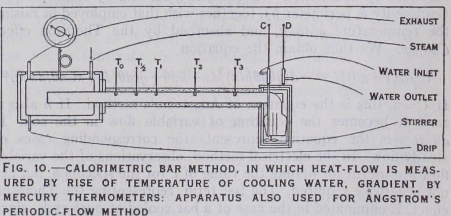
Calorimetric Bar Method.—To avoid the uncertainties of sur face loss of heat, it is necessary to reduce it to the rank of a small correction by employing a large bar and protecting it from loss of heat. The heat transmitted should be measured calorimetri cally, and not in terms of the uncertain emissivity. The apparatus shown in fig. Io was constructed by Callendar and Nicolson with this object. The bar was a special sample of cast-iron, the con ductivity of which was required for some experiments on the condensation of steam (Proc. Inst. C.E., 1898). It had a diameter of 4in., and a length of 4ft. between the heater and the calorim eter. The emissivity was reduced to one-quarter by lagging the bar like a steam-pipe to a thickness of 'in. The heating vessel could be maintained at a steady temperature by high-pressure steam. The other end was maintained at a temperature near that of the air by a steady stream of water flowing through a well lagged vessel surrounding the bar. The heat transmitted was measured by observing the difference of temperature between the inflow and the outflow, and the weight of water which passed in a given time. The gradient near the entrance to the calorimeter was deduced from observations with five thermometers at suitable intervals along the bar. The results obtained by this method at a temperature of 4o° C varied from • I I 6 to • I 18 C.G.S. from ob servations on different days, and were probably more accurate than those obtained by the cylinder method. The same apparatus was employed in another series of experiments by the periodic flow method, but this involves a knowledge of c, and is very laborious.
35. Electrical Methods.—There are two electrical methods which have been recently applied to the measurement of the con ductivity of metals, (a) the resistance method, devised by Callen dar, and applied by him, and also by R. O. King and J. D. Duncan, (b) the thermo-electric method, devised by Kohlrausch, and applied by W. Jaeger and H. Dieselhorst. Both methods depend on the observation of the steady distribution of temper ature in a bar or wire heated by an electric current. The advan tage is that the quantities of heat are measured directly in abso lute measure, in terms of the current, and that the results are independent of a knowledge of the specific heat. Incidentally it is possible to regulate the heat supply more perfectly than in non-electric methods.
(a) In the practice of the resistance method, both ends of a short bar are kept at a steady temperature by means of solid copper blocks provided with a water circulation, and the whole is surrounded by a jacket at the same temperature, which is taken as the zero of reference. The bar is heated by a steady electric current, which may be adjusted so that the external loss of heat from the surface of the bar is compensated by the increase of re sistance of the bar with rise of temperature. In this case the curve representing the distribution of temperature is a parabola, and the conductivity k is deduced from the mean rise of temperature by observing the increase of resistance of the bar, and the current C. It is also necessary to measure the cross section q, the length 1, and the temperature-coefficient a for the range of the experiment.
In the general case the distribution of temperature is observed by means of a number of potential leads. The differential equation for the distribution of temperature in this case includes the ma jority of the methods already considered, and may be stated as follows. The heat generated by the current C at a point x, where O=excess temperature, is equal per unit length and time (t) to that lost by conduction —d(qkdO/dx)/dx, and by radiation hp O (emissivity h, perimeter p), together with that employed in raising the temperature qcdO/dt, and absorbed by the Thomson effect CdO/d.r. We thus obtain the equation +aO) / l = — d (qkdO/dx) /dx+h pO+qcdO/dt +sCdO/dx. (9) If this is the equation of Angstrom's method. If h also is zero, it becomes the equation of variable flow in the soil. If dO/dt =o, the equation represents the corresponding cases of steady flow. In the electrical method, observations of the variable flow are useful for finding the value of c for the specimen, but .re not otherwise required. The last term, representing the Thomson effect, is eliminated in the case of a bar cooled at both ends, since it is opposite in the two halves, but may be determined by observ ing the resistance of each half separately. If the current C is chosen so that the external heat-loss is compensated by the variation of resistance with temperature. In this case the solution of the equation reduces to the form O = (io) By a property of the parabola, the mean temperature is two thirds of the maximum temperature; we have therefore (II) which gives the conductivity directly in terms of the quantities actually observed. If the dimensions of the bar are suitably chosen, the distribution of temperature is always very nearly parabolic, so that it is not necessary to determine the value of the critical current very accurately, as the correction for external loss is a small percentage in any case. The chief difficulty is that of measuring the small change of resistance accurately, and of avoiding errors from accidental thermo-electric effects. In addition to the simple measurements of the conductivity (M`Gill College, 1895-1896), some very elaborate experiments were made by King (Proc. Amer. Acad., June 1898) on the temperature dis tribution in the case of long bars with a view to measuring the Thomson effect. Duncan (M`Gill College Reports, 1899), using the simple method under King's supervision, found the conduc tivity of very pure copper to be 1 •007 for a temperature of 33° C.
(b) The method of Kohlrausch, as carried out by Jaeger and Dieselhorst (Berlin Acad., July 1899), consists in observing the difference of temperature between the centre and the ends of the bar by means of insulated thermocouples. Neglecting the exter nal heat-loss, and the variation of the thermal and electric con ductivities k and k', we obtain, as before, for the difference of temperature between the centre and ends, the equation Omaz — = = ECl/8qk = (I 2) where E is the difference of electric potential between the ends. Lorenz, assuming that the ratio k/k'=aO, had given which is practically identical with the preceding for small differ ences of temperature. The last expression in terms of k/k' is very simple, but the first is more useful in practice, as the quantities actually measured are E, C, q, and the difference of tempera ture. The current C was measured in the usual way by the differ ence of potential on a standard resistance. The external heat-loss was estimated by varying the temperature of the jacket surround ing the bar, and applying a suitable correction to the observed difference of temperature. But the method (a) previously de scribed appears to be preferable in this respect, since it is better to keep the jacket at the same temperature as the end-blocks. Moreover, the variation of thermal conductivity with tempera ture is small and uncertain, whereas the variation of electrical conductivity is large and can be accurately determined, and may therefore be legitimately utilized for eliminating the external heat-loss.
One of the chief objects of these experiments was to test the combined hypotheses of G. Wiedemann (1853) and L. Lorenz (1872), that the ratio of the thermal to the electrical conductivity was the same for all metals, and varied directly as the absolute temperature. This relation was strongly supported as a result of the development of the electron theory of conduction in metals by Drude (1900) and H. A. Lorentz (19o5), and was approxi mately verified for some of the pure metals by Jaeger and Diesel horst between o° and Ioo° C. But the ratio appears to be affected in a marked degree by the presence of impurities which reduce the electric conductivity, and the majority of alloys give much higher values than the pure metals. It has since been shown by the experiments of Lees (1908), Onnes (1914) and Meissner (1920), that the remarkable increase of electric conductivity of some pure metals at very low temperatures does not extend to the thermal conductivity. Sir J. J. Thomson in his Corpuscular Theory of Matter (1907) had already pointed out that there were serious difficulties in the electron theory of Drude and Lorentz, and pro posed an alternative theory which did not require the presence of a large number of free electrons in the metal. This was further developed (Proc. Phys. Soc. 1915) and appears to supply a reason able explanation of the increase of electric conductivity at very low temperatures without requiring a similar increase of thermal conductivity. There is no doubt a general parallelism between thermal and electric conductivity in the case of pure metals, but the conditions are so different in many ways that one could not expect any simple and exact relation to hold generally.