
GYROSCOPE, a rotating wheel universally mounted, i.e., mounted in such a way that it is free to rotate about any axis. This definition is within the scientific meaning of the term, though differences of opinion exist as to the precise meaning of the word "gyroscope." Some writers use the term "gyrostat" to describe a rotatable wheel suspended with its freedom partly or wholly suppressed about one axis other than the axis of rotation. In almost every case where a gyroscope is applied to a practical pur pose, its freedom is either restrained, or controlled in some man ner in order to gain the desired result. One of the first instru ments was that of Bohnenberger, which was constructed as early as 181 o, and is described in Gilbert's Annalen for 1818 (vol. lx., p. 6o). It consisted of a heavy spheroid which could rotate, inside a circular ring, about its shorter axis,—the axis running on pivots situated at opposite ends of the ring's diameter. This ring with its contained spheroid was similarly made movable, inside a second ring, about an axis at right-angles to the axis of the spheroid. In the same way this second ring with its contents could rotate, in side a third ring, about an axis at right-angles to each of the others. From this it will be seen that the spheroid had all degrees of free rotation, one point only within it being fixed, viz., the intersection of the three axes.
In 1836, in a paper read bef ore the Royal Scottish Society of Arts, Edward Lang suggested an experiment with an instrument exactly similar to the gyroscope, by which the rotation of the earth on its axis could be directly proved. He says : "While using Troughton's top an idea occurred to me that a similar principle might be applied to the exhibition of the rotation of the earth. Conceive a large flat wheel, poised on several axes all passing directly through its centre of gravity, and whose axis of motion is coincident with its principal axis of permanent rotation, to be put in very rapid motion. The direction of its axis would then remain unchanged. But the directions of all surrounding objects varying, on account of the motion of the earth, it would result that the axis of the revolving wheel would appear to move slowly." This suggested experiment was actually carried out, in 1852, by Leon Foucault, probably without any knowledge of Lang's sug gestion. The name gyroscope was given to the instrument by Foucault at this time, and the experiment, repeated at the Liver pool meeting of the British Association, caused such a sensation that the gyroscope was brought to the notice of the public. In order to perform these early experiments successfully it was nec essary to construct the instrument with the utmost exactness. Further difficulty hindered the development of the gyroscope, in that rotation could not be kept up for any length of time without functional interference causing the rotor to be inaccurate. Con sequently, until comparatively recently, the gyroscope remained largely an instrument used only for demonstration purposes. It was not until the latter part of the i9th century, when G. M.
Hopkins introduced the first elec trically driven rotor, that the utility of the gyroscope could be fully realized.
Fundamental Principles of t h e Gyroscope. — Gyroscopic phenomena are exhibited in all rotating bodies, but are more evi dent in those possessing large angular momentum. The angu lar momentum of a rotating body is dependent directly on the weight of the body, on the square of the distance at which the mass is situated from the axis of rota tion and on the speed of rotation. It is therefore obvious that, for gyroscopic action to be pronounced, the spinning wheel should be heavy, the material should be disposed as far as practicable from the axis of rotation and the speed of rotation should be as high as feasible. A gyroscopic wheel should be well balanced, and mounted to permit rotation at high speed while free to move about any axis.
Elementary Gyroscope.—The ways in which gyroscopic wheels are mounted are various, and depend upon the duties they are to perform. The type illustrated in fig. i is the most familiar form for general study. This type of elementary gyroscope is a balanced wheel mounted so as to be free to spin with its axle in any direc tion, i.e., it has three degrees of freedom. The three degrees of freedom of the elementary gyroscope (fig. 1) are the following: (1) The wheel is free to rotate (spin) about its "spinning" axis, the wheel's axle. (2) The wheel (with its axle and axle bearings) is free to rotate about the "vertical" axis, which axis is in the plane of the wheel and intersects the spinning axis at right angles. (3) The wheel (with its axle, axle bearing, vertical axis and vertical axis bearings) is free to rotate about the "horizontal" axis, which axis intersects the vertical axis at right-angles at the intersection with the spinning axis. The spinning and vertical axes are always at right-angles to each other, as are also the horizontal and cal axes, but the spinning axis may make any angle with the horizontal axis. The spinning axis may also be in any direction horizontally, and therefore in any direction relative to space.
Gyroscopic Properties and Rigidity.
—All known gyroscopic phenomena and the application of the principles involved are dependent upon two properties of the elementary gyroscope ; viz.: (1) Rigidity in space (actually gyroscopic inertia) . (2) Precession.
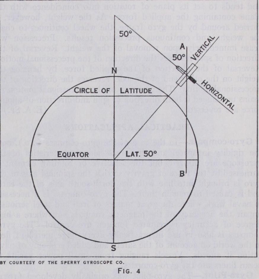
Rigidity relative to space is illustrated by the following experi ments and considerations : On spinning the gyro-wheel in either direction, it will be found to have assumed a rigidity of direction of its axle and plane of rotation relative to space. It can be carried about on its support, which may be turned in any direction, with out alteration of the direction of its axis relative to space. If a gyroscope having complete freedom is so made that it can spin continuously and is sufficiently frictionless in its supports, it will, if used in the following manner, demonstrate its gyroscopic inertia, the property referred to as "rigidity in space." If such a gyroscope is set at the earth's equator, with its spinning axis hori zontal in the east and west direction (see figs. 2 and 3) and is spin ning continuously, then the wheel, while spinning, will also appar ently rotate about a horizontal axis which is at right-angles to the spinning axis. This apparent rotation will proceed at the rate of one revolution in one day. Actually, however, the gyro spinning axis has remained parallel to its original position in space, though the gyroscope has been carried along with the earth by the revolu tion of the latter about its polar axis. Thus (fig. 4) at the end of three hours the west end of the axle viewed looking north as above will be depressed and at the end of six hours it will be vertical (to the surface of the earth), having been carried through a quarter revolution in a quarter of a day. At the end of 12 hours it will again be horizontal but with its ends reversed, as viewed by the observer looking north; but actually the gyro axle will still be parallel to its original position in space and pointing in its original direction in space. At the end of one complete revo lution of the earth the original position of the gyro axle is regained.
This and similar gyroscopic phenomena are the result of the action of forces affecting the state of rest and motion of the gyroscope in the manner expressed by Newton's First Law of Motion, which states that every body continues in its state of rest or uniform motion in a straight line, unless it is compelled by forces to change that state. This law, as applied to a rotating wheel, may be expressed by stating that a rotating wheel tends to maintain the direction of its plane of rotation in space and the direction of its axis in space. A gyroscopic wheel at rest, or any balanced mass at rest with corresponding freedom to move, would show similar phenomena when moved about, if there were no friction. Friction cannot be eliminated entirely, but may be reduced to a minimum by ball-bearing pivots, etc. (see BEARINGS). For a rotating wheel, friction can be reduced to an almost neg ligible amount in comparison with the forces necessary to disturb the plane of rotation. For a gyroscope with complete freedom, set spinning at either the North or South Pole of the earth, with the gyro axis horizontal, the latter will be at right-angles to the polar axis of the earth. As, however, the spinning gyroscope will maintain the direction of its plane of rotation in space and the direction of its axis in space, though the earth rotates under it, the gyro will have an apparent motion about the polar axis, so that the gyroscope appears to rotate about its vertical axis while spinning about its axle.
The apparent motion will be in a direction counter to the direction of rotation of the earth about its polar axis. The appar ent motion of the gyroscope about its vertical axis will theref ore appear clockwise as viewed looking toward the earth at the north pole, and counter-clockwise as viewed looking toward the earth at the south pole, the direction of view of the earth's rotation being the reverse at the South Pole to the direction of view at the North Pole. It should be noted that, at the Poles, the apparent rotation is entirely about a vertical axis, but at the equator the apparent rotation is entirely about a horizontal axis. For a gyro scope with complete freedom, set spinning at some intermediate latitude, with the gyro axle horizontal and in the meridian, the gyro axle will neither be parallel to nor at right-angles to the earth's axis, but will be at an angle to it equal to the latitude, and therefore also at the equal angle to a line which passes through the centre of the gyroscope and is parallel to the polar axis of the earth as indicated in fig. 5.

Apparent Rotation.—Rigidity of direction in space, or gyro scopic inertia, will therefore cause the gyro axis apparently to rotate about a line A-B (fig. 4), passing through the centre of the gyroscope and parallel to the polar axis of the earth. This appar ent movement of the gyro axle, will be with a daily period and will be partly about the vertical line passing through the centre of the gyroscope and the centre of the earth, and partly about the "horizontal" axis of the gyroscope. This "horizontal" axis (see fig. 3) should not be confused with the gyro axis which is in the horizontal position (fig. 4) only momentarily during each day for the conditions assumed. The earth's axis is, for the time, con sidered as fixed in direction in space and it serves as a convenient base-line from which to observe certain gyroscopic and directional phenomena.
This property may be illustrated experimentally. Fig. 5 shows a wheel mounted so as to have three degrees of freedom and, for convenience of experiment, set with its spinning axis horizontal.
On spinning the gyroscopic wheel in the direction indicated by the arrow B and applying force F to turn the gyroscope about the horizontal axis, it will be found that there is a great resistance to the force, and, instead of motion taking place in the direction of the applied force, that the wheel turns around in the direction of the arrow P and will continue to turn in that direction during application of the force until the plane of spin of the wheel coincides with the plane of the force. Then the wheel not only ceases to turn in the direction of the arrow P, but the resistance to the applied force F also ceases, and accordingly the gyro will be turned about its horizontal axis by the force F. Furthermore, the wheel will cease turning around in the direction of the arrow P, not only when the two planes coincide but also as soon as the application of the force is interrupted, though the axes have not reached a point of coincidence at that time. In other words, not only does pre cession cease at any stage on removal of the force but the gyroscope offers no further resistance to the impressed force once the plane of spinning rotation becomes coinci dent with that of the applied force. Re versing the direction of spin and repeating the experiment (fig. 6), similar phenomena will be exhibited, except that the wheel turns in the opposite direc tion. This precession is always about an axis at right-angles to the axis of the impressed force.
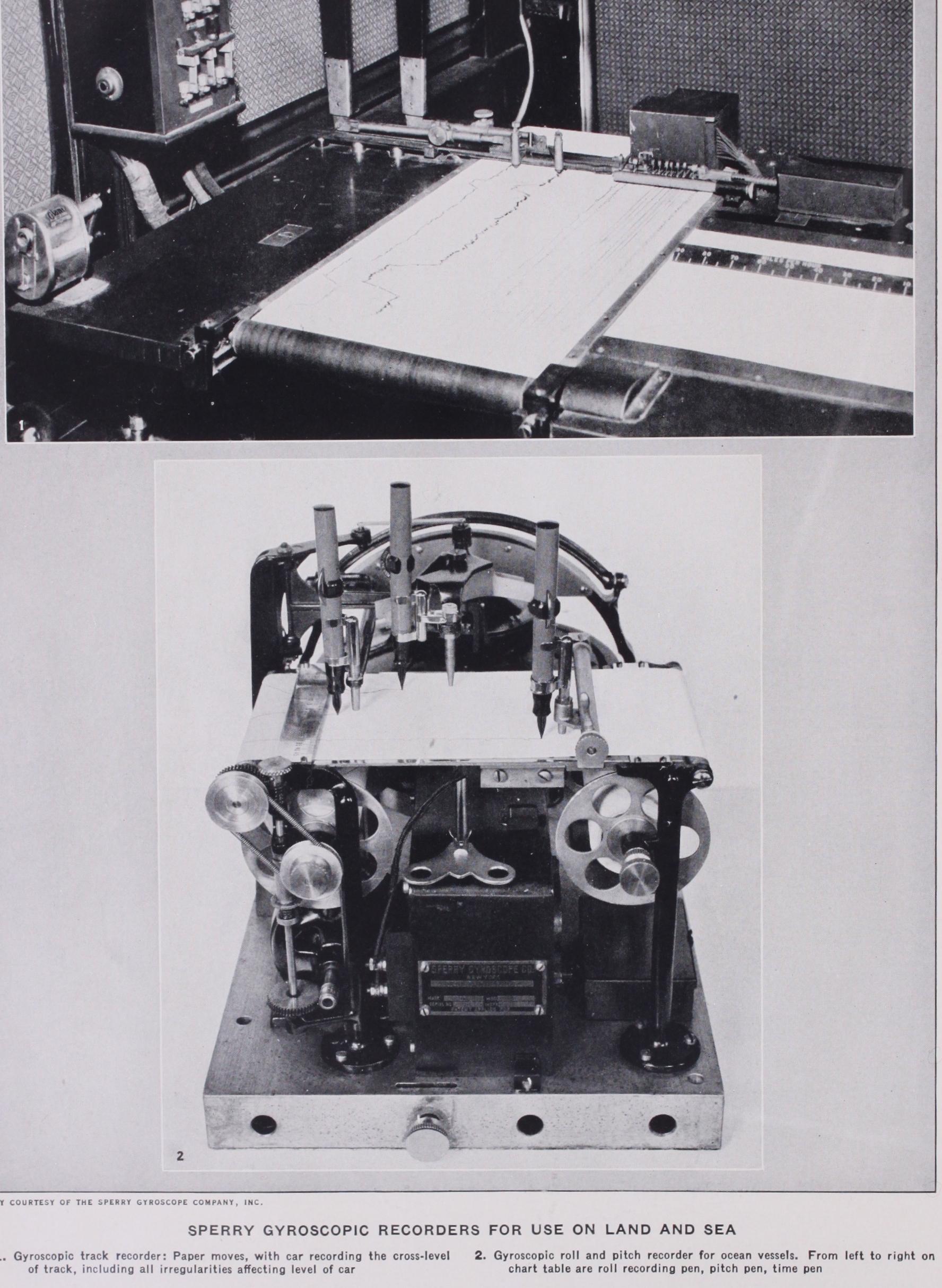
Continuous Precession.—When the couple acting on the gyro system is arranged in such a way that it and the plane containing it are caused to rotate with the precession, the latter becomes con tinuous. This is illustrated in fig. 7, showing a spinning gyro with horizontal axle and with a weight hung at one end of the axle. Instead of turning over under the pull exerted by gravitational force on the weight, as would be the case if the wheel were not spinning, the spinning wheel will turn about its axis, as indicated at P in fig. 7. The axis about which the wheel spins is at right angles to the axis of the applied force in the instance illustrated, and tends to set its plane of rotation into coincidence with the plane containing the applied force. As the weight, however, is carried around by the gyro 'frame, the wheel continues to chase the weight and continuous precession results. Precession will cease immediately upon removal of the weight. Reversal of the direction of spin reverses the direction of the precessional motion. Reversal of the direction of the applied force, by hanging the weight on the other end of the axle, reverses the direction of the precessional motion. The direction of the precessional motion re mains unchanged if both direction of spin and direction of applied force are reversed. (E. A. SP.) Gyro-compass.—In the case of the gyro-compass (q.v.), both the rigidity in space, and the precession characteristics of the gyroscope are utilized, but the sensitive or rotating element is harnessed by the force of gravity so that the spinning axis of the gyro is brought into line with the north-south axis of the earth and is caused to remain there. The gyro-compass is a necessity in naval work where the great masses of iron and steel seriously impair the accuracy of the magnetic compass and where a high degree of accuracy is required for gun fire control. The gyro compass is also in use in practically every large merchant fleet in the world on account of the safety and added economy of navi gation it affords. Vessels ranging from small power yachts to ocean liners use the gyro-compass.
A gyro-pilot was therefore produced (1925) having a control unit or steering stand, containing the gyro-compass repeater, on the bridge, and a power unit in the steering engine room attached directly to the steering gear control. With this arrangement the output of the steering stand in the wheelhouse is transmitted to the power unit aft by an independent electrical system which parallels the existing ship's telemotor. Through this system course changes may be effected while steering automatically, and the ship may also be steered manually by means of a wheel on the steering stand.
Facilities are provided in the equipment to take care of vari able factors which influence the steering of the vessel. Under certain conditions, for instance, it is desirable to let the vessel have a small amount of "weather yaw." An adjustment is pro vided on the bridge unit for this purpose. Another adjustment varies the amount of rudder applied for a given amount of de parture from the set course. It will be seen, therefore, that the gyro-pilot can steer a loaded ship as well as it can a light one and that it is effective in heavy weather as well as in a smooth sea.

The Sperry gyro-magnetic compass combines the fundamental north-seeking characteristics of the magnetic compass with the directional stability of the gyroscope. It provides an accurate and steady indication of magnetic heading at all times. The mag netic compass does not give accurate directional information dur ing disturbances and turns. The directional gyro is an accurate index of turn but requires occasional resetting. When used in conjunction with each other, however, they provide an adequate reference for navigation. In the gyro-magnetic compass the mag netic element directs the gyroscope to the magnetic heading, and the gyroscope stabilizes the magnetic element against disturbing influences such as northerly turning error, dip, and acceleration forces. Hence the individual limitations of the magnetic compass and the directional gyro when used independently are completely overcome when the instruments are properly combined as in the gyro-magnetic compass.
Gyroscopes are used extensively in naval warfare to control torpedoes. The rotor of one of these instruments is given an initial spin (by means of compressed air) either just before or at the time when the torpedo is leaving the tube. It is designed to revolve at a high rate of speed for about 15 min., or as long as the torpedo continues to move through the water. The "rigidity of space" characteristic of the gyroscope only is employed in this case.
The gyroscope, by means of air pressure, controls a small steer ing engine in the after part of the torpedo which actuates the rudders. (R. E. G.) See R. F. Deimel, Mechanics of the Gyroscope (1928).