FIXED BRIDGES An independent span, one that reaches from abutment to abutment, or pier to pier, without projecting beyond the supports. The stresses set up by its own weight, or dead load, and by the loads that pass over it, or moving or live load, can be calculated with great accuracy, and it is therefore known as a determinate structure. Bridges of this type usually consist of main girders placed below or above the platform they support, the girders having top and bottom booms, either curved or straight, con nected together by web systems of many different types each with its own advantages and name. The girders are proportioned so that the depth is usually from one-eighth to one-twelfth of the span, the greater the depth the stiffer being the girder. The top boom is in compression while the bottom is in tension, the web members being in tension or compression according to their posi tion. The limiting span for this type is about Boo feet. Fig. i illustrates Hawkesbury bridge in Australia with seven spans of 416f t. each.

those that reach over more than one open ing, usually three. They have the advantage of being lighter and of being deflected less than independent spans, but the stresses are more difficult to determine and great change of stress takes place in them if the supporting piers subside by even a small amount. While largely discarded in Europe, this type of bridge is being increasingly developed in America. However, in addition to the problems of stress, this type has the disadvantage of alterations in length, due to temperature, which are difficult to arrange for, as they represent the total variations of several openings. Britannia bridge (fig. 2), with two spans of 46oft., and two of 23oft., is continuous over all three piers, and the expansion and contraction to be dealt with at each end amounts to a total of 4 inches.
probably the most graceful type of all, can be constructed in many different materials. An arch usually consists of part of a solid ring or of a series of arched ribs, backed up by solid or open spandrils until a level line is reached upon which the floor or deck is constructed. The arched ring or ribs spring from sloping surfaces called skewbacks formed in the abutments and piers. The stresses in an arch are difficult to determine, and the calculations have to be based upon certain more or less arbitrary assumptions. With a view to making the structure conform with the calculations, especially in the case of large metal ribs, round pins are inserted at the skewbacks, and in some cases at the centre as well, to ensure that the stresses pass through these points. Arches are known according to the number of pins, as no-pinned, two-pinned or three-pinned, and in the latter case the stresses are quite determinate.
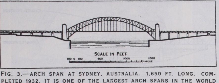
The usual proportion of rise of arch to span is about one-tenth, and the depth of the arch ring, or ribs, varies from about one twenty-fifth of the span in the case of masonry structures, to about one-fortieth in a steel rib. In all arches the arch ring is in compression under the permanent or dead load, but when heavy moving or live loads pass over the bridge, reversals of stress may take place that may lead to the distortion and failure of the arch if these have not been allowed for in the design. Arches up to about 400f t. span have been constructed in masonry or reinforced concrete and, until recently, 600ft. has been considered the limit for mild steel, but with the advance in the knowledge of the theory of structures, Hell Gate bridge, New York, with a span of i,oi7ft., has been successfully completed, and Sydney bridge, Australia (fig. 3) with a span of 1,65o ft. was completed in 1932. This bridge is one of the largest arch-spans in the world. It was designed as a two-pinned arch and carries a roadway 57 ft. wide, together with four railway tracks and two footpaths ; its total width is 160 feet. Its estimated cost was Ł4,200,000.
In the United States increasing numbers of arch bridges, of con crete or reinforced concrete, have been constructed since the World War, especially in connection with the development of streets and highways. Noteworthy examples are the Hampden County Memorial bridge at Springfield, Mass. ; the Cappelen Me morial bridge at Minneapolis, Minn. ; the Arroyo Seco bridge at Pasadena, Calif.; the Ft. Snelling-Mendota bridge in Minnesota; and the Memorial bridge at Wilmington, Delaware.
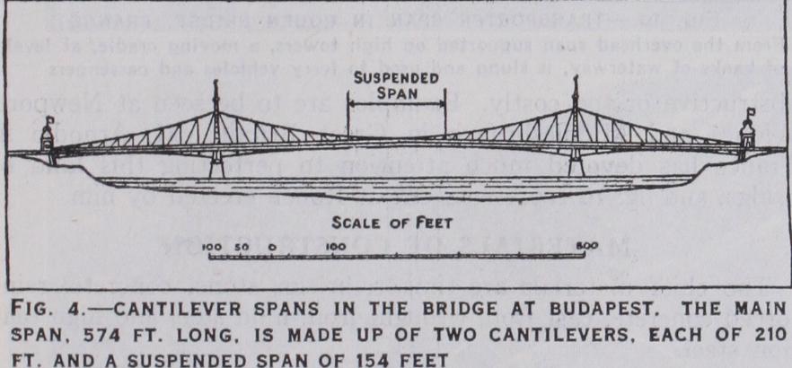
type is often adopted when large spans have to be constructed, the limiting size being as high as about 3,000 feet. The principle is that of two projecting arms reaching towards each other, the gap between their ends being bridged by means of an independent, or suspended, span. The weight of all these is balanced by projecting arms reaching shorewards and anchored down. The stresses are quite determinate but, as in all large structures, the calculations are laborious and many secondary stresses have to be investigated. The effect of wind on large structures of this type is very serious and, in the Forth bridge, with spans of i,7ioft., the amount of steel provided to resist the stresses set up by this agency amounts to 47% of the total weight of the cantilevers. Fig. 4 shows the cantilever bridge at Budapest with a main span of 5 74f t. made up of two cantilevers of 2 r of t. and a suspended span of '54 feet.
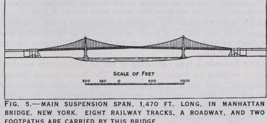
a type which lends itself readily to the con struction of the largest spans, the theoretical limit being in the neighbourhood of 7,000 feet. Camden bridge over the Delaware river has been constructed with a span of 1,75oft., and a bridge of double this span has been commenced over the Hudson river at New York. A suspension bridge consists of steel wire ropes or steel links of high tensile strength passing over lofty towers and anchored at each end. The platform for the roadway is suspended from the main ropes or chains by means of vertical ropes, and the change of form and swaying set up by moving loads is largely reduced by means of horizontal stiffening girders placed at road level. This type is not usually adopted for railway bridges on account of the changes of form that take place in spite of the stiffening girders. However, in large spans the inertia of the dead weight of the bridge is so great that this difficulty has been largely overcome, and both the completed large suspension bridges re ferred to above, together with others of older date, have railway tracks on them. Manhattan bridge, New York (fig. 5), constructed 1903-9, carries eight railway tracks, together with a roadway 3 5f t. wide and two footpaths.