
BRIDGING, MILITARY. In the course of most military operations it is necessary to cross rivers at places where no bridges exist or where they have been demolished by the enemy. It is the duty of the engineers of an army to provide the means for such crossings. For small detachments ferrying with boats or rafts is resorted to, but for forces of any size accompanied by artillery and transport bridges must be built. Floating bridges are the most rapidly built and have consequently been most frequently employed ; they are built either with material obtained locally or with special "pontoon" equipment accompanying the army on wagons. Many other types of construction have been employed such as trestle bridges in which the roadway is supported by a series of timber trestles, cribwork bridges in which the supports consist of timber cribs usually filled with stone, pile bridges, sus pension bridges and steel or wooden girder bridges. So long as transport and guns were drawn by animals the weight of vehicles was limited and consequently the strength required of military bridges remained approximately constant until the beginning of the loth century. With the introduction of motor vehicles and tanks, however, weights increased enormously and all bridging standards had to be reconsidered.
From time immemorial floating bridges of vessels bearing a roadway of beams and planks have been employed for the passage of rivers and arms of the sea. Xerxes crossed the Hellespont on a double bridge, one line supported on 36o, the other on 314 vessels anchored head and stern with their keels in the direction of the current. Darius threw similar bridges across the Bosphorus and the Danube in his war against the Scythians, and the Ten Thou sand employed a bridge of boats to cross the river Tigris in their retreat from Persia. Floating bridges have been repeatedly con structed over rivers in Europe and Asia, not merely temporarily for the passage of an army, but permanently for the requirements of the country; and to this day many of the great rivers in India are crossed by floating bridges which are for the most part sup ported on boats such as are employed for ordinary traffic on the river. Alexander the Great is said to have carried his army over the Oxus by means of rafts made of the hide tents of his soldiers stuffed with straw when he found that all the river boats had been burnt. Cyrus crossed the Euphrates on stuffed skins. In the 4th century the emperor Julian crossed the Tigris, Euphrates and other rivers by bridges of boats made of skins stretched over osier frames. In more recent times bridges have been supported on floating piers made of barrels lashed together. During the World War light footbridges for the assaulting infantry were frequently made supported by floats composed of cork or empty petrol tins held together in light crates. Bivouac sheets stuffed with straw were also used as in the days of Cyrus and Alexander.
The pontoons must have sufficient buoyancy to support the loads which are to use the bridge ; within limits the power of support can be increased by placing them closer together, but in rapid currents the water-way must not be unduly obstructed or the bridge will be washed away. They must be light enough to be man handled and to be loaded upon wagons. They must be strong enough to withstand rough usage and should be easily repairable in the field. These requirements are contradictory and the history of pontoon design is a history of compromise. The most usual form is that of a flat-bottomed boat either with or without a deck; decked it can with safety be more deeply loaded, but its interior is inaccessible and it is less convenient for use as a boat.
The road-bearers must be strong enough to support the road way, and must also be as light as possible for transport. Evi dently, the greater the intervals between the pontoons the greater the strength required. They may rest either on a central saddle placed longitudinally on each pontoon vertically above the keel— "saddle loading"—or simply upon the gunnels of the pontoons— "gunnel loading." Saddle loading makes for great simplicity in constructing the bridge, each set of road-bearers spanning from the centre of one pontoon to the next with claws or pins on their ends which engage in the saddles. Gunnel loading does not require such strong road-bearers since the spans are shorter; it also adds stiffness to the bridge, but the fastenings are more complicated. Until the advent of mechanical transport wooden road-bearers about Sin. by 4in. in section and 15 to 2oft. long were usually employed.
The chesses must be as light as is consistent with strength. In the days of horse-drawn traffic I lin. was the usual thickness; for heavy traffic a second layer was laid on top of the first.
During the 19th century a great number of designs were intro duced only a few of which can be mentioned here. No army had more experience of pontooning than the French; during the wars of the Revolution and the Empire they constructed pontoon bridges over most of the principal rivers of Europe. They experi mented with many types ranging from large wooden boats weigh ing about 2 tons to small copper ones weighing 7cwt. ; the heavy wooden type, the Gribeauval, was discarded in 18o5 as it could not keep up with the movements of the armies; in 1853 they adopted a flat-bottomed open wooden boat 3i ft. long and weighing 1,45o lb., which appears to have been very successful and was exten sively used by the Northern States during the American Civil War.
During the Peninsular War the English employed open pontoons, but the experience gained during that war induced them to intro duce the closed form. Gen. Colleton devised a buoy pontoon, cylindrical with conical ends and made of wooden staves like a cask. Then Gen. Sir Charles Pasley introduced demi-pontoons, like decked canoes with pointed bows and square sterns, a pair, attached stern-wise, forming a single "pier" of support for the roadway; they were constructed of light timber frames covered with sheet copper and were decked with wood ; each demi-pontoon was divided into watertight compartments and provided with means for pumping out water ; for transport a pair of demi-pon toons and the superstructure for one bay of bridge were loaded on, a single wagon. The Pasley was superseded by the Blanshard pontoon, a tin-coated cylinder with hemispherical ends for which great mobility was claimed, two pontoons and two bays of super structure being carried on one wagon. The Blanshard pontoon was long used in the British army, but was ultimately discarded, and British engineers reverted to the open pontoon to which the engineers of all the Continental armies had meanwhile constantly adhered. Capt. Fowke, R.E., invented a folding open boat made of waterproof canvas attached to sliding ribs, so that for trans port it could be collapsed like the bellows of an accordion and for use could be extended by a pair of stretchers. This was fol lowed by a pontoon designed by Col. Blood, R.E., an open boat with decked ends and sides partly decked where the rowlocks were fixed. The sides and bottom were of thin yellow pine with canvas secured to both surfaces with india-rubber solution, and coated outside with marine glue. The central interval between the pon toons in a bridge was r 5f t.; five baulks were ordinarily used, nine for the passage of siege artillery and the heaviest loads ; saddle loading was employed. One pontoon with one bay of superstruc ture were loaded on a wagon. This equipment was later modified by the introduction of an undecked bipartite pontoon designed in 1889 by Lieut. Clauson, R.E. As its name implies this pontoon was in two sections, a bow section and a stern section, coupled together with easily manipulated couplings of phosphor bronze. For light bridges the sections could be used independently; for heavy bridges three sections could be coupled together end to end. Except for minor modifications this equipment was retained in the British service until 1924. During the World War it was much used in Mesopotamia and during the early and final stages in France ; it was found unsuitable in the rapid current of the Piave on the Italian front.

Historically the most important equipment is that introduced in the Austrian army by Col. Birago in 1841 ; it was either adopted or copied by many other armies. The Birago pontoon was a flat bottomed open boat constructed in sections two or more of which could be coupled together end to end to form piers of the buoy ancy required. This idea had first been proposed by Col. Pompei Floriani about the middle of the 17th century but had not pre viously been fully developed ; as already mentioned it was subse quently adopted in British equipments. The Birago pontoons were in the first instance made of wood, later they were made en tirely in iron and later still in steel. One reason given for the change was that metal pontoons were more easily repaired in the field than wooden ones ; this argument, however, would not gen erally be accepted. Saddle loading was adopted, the saddle being arranged to slew in the pontoon so that a bridge could be built diagonally across a river, the pontoons still pointing in the direc tion of the current ; great importance was attached to this feature at the time but it was not subsequently found to be practical.
An interesting equipment was introduced into the American army in 1846. The pontoons were made entirely of india-rubber and each consisted of three parallel pointed cylinders croft. long joined together side by side by an india-rubber web. When the pontoon was required for use these cylinders were inflated through nozzles with a pair of bellows ; for transport the entire pontoon was folded up and packed in a box. After considerable experience during the American Civil War the engineers of the Northern States much preferred the French equipment.
Methods of Bridge Building with Pontoon Equipment.— There are f our recognized methods of building pontoon bridges; the choice depends partly upon the actual equipment in use and more upon the site of the bridge and nature of the river. (a) "Forming up." In this method pontoons are added successively to the "head" or far end of the bridge and the roadway added on top of them; this is perhaps the simplest method. (b) "Boom ing out." Pontoons are added successively at the "Tail" or shore end and the whole bridge pushed out, this saves carrying all the stores for the roadway to the far end of the bridge. (c) "By rafts." Complete sections of the bridge are built in convenient positions by the near bank, floated into position and joined to gether; this method will often be quicker than (a) or (b). (d) "Swinging Bridge." The entire bridge is built alongside the near bank, that is, at right angles to its final position; when complete it is allowed to swing round with the current on its near end as a pivot, anchors are dropped in their appropriate positions as it swings and the entire bridge is checked by the anchor cables as it reaches its correct alignment. On a suitable site this method is extremely rapid, but in fast streams the operation is risky and the bridge often is lost or severely damaged.
Girder Br idges.—Unlike the types described above girder bridges can span clear gaps of iooft. or more without any inter mediate support. They were first extensively used during the World War in France. Standard patterns were manufactured in large quantities, parts were as far as possible interchangeable and bridges could be built of any multiple of the fixed panel length up to a maximum which depended on the loads which were to use them. The Hopkins type of girder bridge and the Inglis were the most important types; both were "through" bridges, the roadway being carried between two Warren girders. The Hopkins followed the lines of ordinary civil practice except that bolts were substi tuted for rivets to facilitate erection in the field. In the Inglis the principal members were tubular and were connected into special cast junction pieces by pins and locking rings. The method usually employed was to build the bridge on dry land in rear of the gap and then launch it over rollers by means of derricks and winches on the far bank.
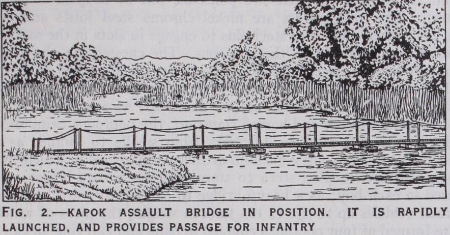
The operation of launching and pushing the bridge across the river can be effected in a few seconds, and as soon as it has been secured on the far bank the assaulting infantry can commence to cross. The articulation of the saddle joint allows sufficient play for the bridge to be carried and launched over rough ground whilst providing sufficient lateral rigidity to steer its head across the stream, even against cross-wind and current. The buoyancy of the floats is ample and the bridge is stable in the water. The virtue of the kapok float lies in its lightness and in the fact that it is little affected by rifle fire ; even when repeatedly punctured it absorbs water very slowly. For the formation of a bridge to take pack transport three kapok assault bridges are placed side by side and planked over to form a roadway.
The French have adopted an undecked pontoon made of gal vanized steel sheet on a steel framework; it is 33 f t. long, 6f t. 6in. wide and aft. Sin. deep, weighs 2,420 lb. and is designed for gun nel loading. Experiments have been carried out with two systems of construction. In the first ordinary wooden road-bearers are used and lashed down to the pontoons ; in the second an ingenious arrangement of articulating steel girders is added outside the roadway on each side to distribute the load between pontoons; the road-bearers in this case are of steel.
It will be seen that there is still wide divergence of opinion as to the best design for a pontoon equipment; on the whole it may be said that the metal pontoon is, in spite of its weight, gaining ground at the expense of the wooden one; that the boat-shaped pontoon has asserted its superiority over all other designs; and that decked pontoons are in the minority. Opinion on saddle versus gunnel loading is divided. Experiments with aluminium alloy pontoons have been undertaken in several countries, but nowhere have the practical difficulties yet been overcome.
Three types of bridge can be built by using two, three or four box girders under the chesses. In fact the gap is to all intents and purposes spanned by using skeleton steel road-bearers which can be made up to any desired length in 8ft. sections. To obtain a wider bridge it is merely necessary to add more box girders and use longer chesses, or a double row of chesses. The decking is held in position by angle steel kerbs fixed down by hook bolts, and the handrail consists of posts which fit into the sockets in the centre of each 8ft. length of kerb and piping. The handrail pipes are also used as carrying bars for carrying sections of the girders. The girders will usually be fitted with horn beams at each end, a construction which enables them to be lowered on to masonry abutments, or on to a timber bankseat so that the level of the roadway may be kept down and a ramp-up approach avoided; but where head-room under the bridge is required or the approach level is suitable, these are not necessary. The girders may be launched by means of a derrick on the far bank or a cantilever method may be adopted if the bridge is a heavy one with three or four girders. In this case each girder is used in turn as a counter-weight for the next, the last girder being rolled across on deck planks laid on those already in position and then jacked down.
The construction of approach roads to a heavy bridge is often a work of greater magnitude than the construction of the bridge itself as they must be sufficiently permanent to carry the heavy strain of mechanical transport. Thus, whilst the assault bridges are intentionally thrown well away from the main lines of traffic and the lighter forms of pontoon bridge can be used wherever a reasonable cross country approach track can be made, the heavy bridges are confined closely to the route of the main roads.
See Official army manuals on bridging (English, French, American, etc.), which are the best source of information. The Work of the Royal Engineers in the European War 1914-1919, Bridging, Institution of Royal Engineers, Chatham (1921) , contains interesting photo graphs. (R. D. D.)