OPENING BRIDGES The Swing Span is probably the most usual type of opening bridge, the structure being pivoted so that it revolves in a hori zontal circle. The arms on each side of the pivot may be of equal length, in which case they balance each other, but if of unequal length, the shorter is provided with weights or kentledge until a balance is reached. In common with all opening bridges the mo tive power may either be human labour or some mechanical power exerted by hydraulic or electric machinery. To reduce the effort required, the weight of the span is usually carried by a number of radially set rollers running on a circular track, the function of the pivot being largely a centring one. The objection to this type of bridge is that the supporting pier, together with its protective works, occupies a large amount of space and if, as is often the case, it is located in the centre of a river, collisions with it are apt to take place, and in any case, valuable width is wasted. The Rodah bridge at Cairo (fig. 6), has a swing span giving two open ings of 65f t. 6in. each, but it will be noticed from the drawing that as much as 67ft. 6in. is taken up by the central support and its protective staging.

a type consisting of one or two counter-weighted leaves working on horizontal pivots. The leaves rotate through about 9o°, and the supporting piers being on each side of the waterway, a clear channel in the middle is provided for traffic. The weight of the leaves is of necessity concentrated on the pivots or trunnions, and this is a very serious matter in large spans. The difficulty has, to some extent, been got over by enlarging the pivots until they are virtually wheels, as in the Schertzer form, but large concentrations of loads seem to be unavoidable with this type of bridge. In the case of the new Schertzer opening bridge at Queens ferry, Chester (fig. 7), the obstruction in the river has been re duced to two small piers, each 'oft. wide, the opening leaves being constructed somewhat narrower than the approach spans and rotating back on to them.
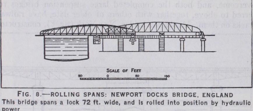
Here the moving span is mounted upon wheels or rollers that allow it to be moved bodily away from the opening at right angles to it, but in order that this may be accom plished, it must either be lifted vertically in order that it can roll back upon the approach, or the approach must be lowered. This is a somewhat complicated arrangement, and not many bridges of this type have been constructed. Fig. 8 shows one of the few constructed in Great Britain and situated at the Newport docks.
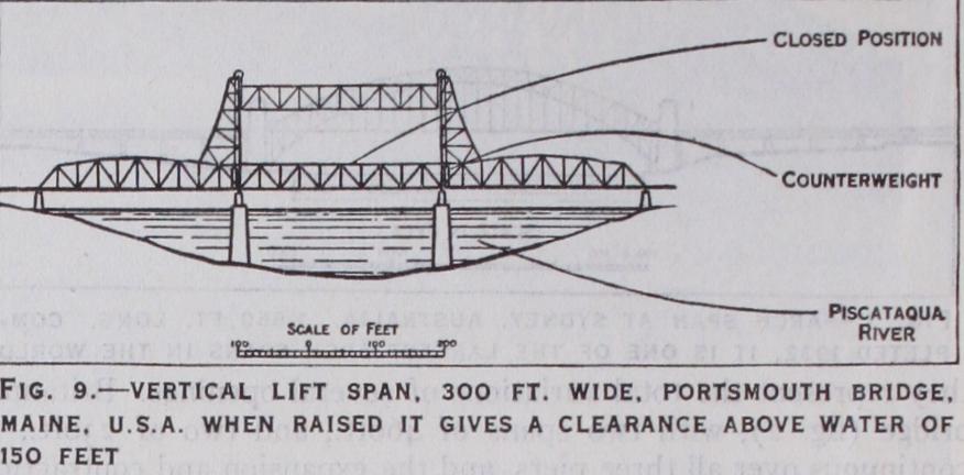
This has many advantages, and quite a number of bridges have been constructed on this principle in recent years in the United States. The weight of the bridge is taken by means of wire ropes that pass over pulleys at the top of tall towers and are then attached to counterweights. The height of the towers is such that when the bridge is raised vertically in the manner of a lift, there is sufficient clearance under the moving span for the river traffic to pass. As the weight of the bridge is balanced by the counterweights, the power required to open it is only that necessary to overcome inertia, together with any friction between the guides fixed to the towers that also serve to keep the moving span in position. The bridge at Portsmouth, Me., U.S.A., (fig. 9), completed in 1924, has a lifting span of 30o feet, and the vertical clearance above high water when open is 15o feet.
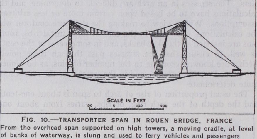
more an aerial ferry than an opening bridge. It consists of an overhead bridge supported on lofty towers, there being a moving cradle on its underside. A platform level with the banks of the opening is slung from the cradle, and on the cradle being set in motion the platform with its load of vehicles and passengers is ferried across the gap. This type has been adopted across wide busy rivers or harbours where the cost of a high level bridge with long approaches would be prohibitive, or where an opening span of a normal type would either be too obstructive or too costly. Examples are to be seen at Newport, Widnes and Middlesbrough in Great Britain. M. Arnodin in France has devoted much attention to perfecting this kind of bridge, and fig. 10 represents one at Rouen erected by him.
The chief materials are timber, bricks, stone, concrete, rein forced concrete, cast iron, wrought iron, mild steel and high ten sion steel.
is now chiefly confined to temporary structures, except in development works in new countries. In order to increase its durability, it is often impregnated with creosote.
if carefully selected, have a life of hundreds of years. They can, of course, only be used in compression, and the safe working stress varies from about 8 tons per sq.ft., in the case of the softer varieties, to
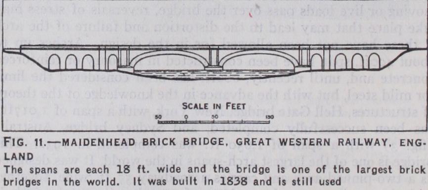
tons per sq.f t. in the harder. The mortar used in setting them usually consists of one part of Portland cement to two parts of clean sand. The Great Western railway bridge at Maidenhead (fig. 11) was constructed in 1838 by Brunel with two spans of 1 28f t. each, and is one of the largest brick bridges in existence. The arches settled when the centring was struck and doubts were expressed as to their stability, but they have stood the test of time well in spite of the fact that the weights of the trains passing over them have greatly increased since their completion.
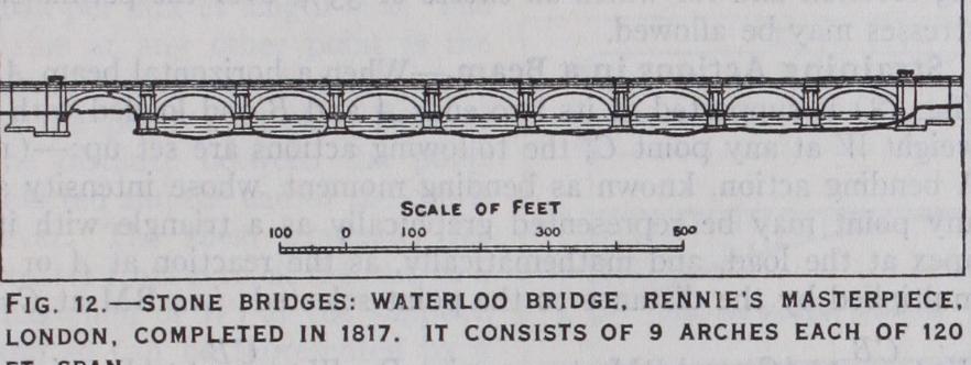
The stone used in bridge construction ought not only to be strong, but it should also be able to resist the disintegrating effects of heat, frost, rain and vibration. The safe working stress in compression is about 20 tons per sq.ft. for limestones and sand stones, increasing to about 3o tons per sq.ft. for granite and similar hard stones. For arched spans up to about 2ooft., stone is the finest material that can be employed, and the resulting struc ture not only satisfies the eye but, if supported in solid founda tions, it should endure for centuries with practically no upkeep. An interesting example is Waterloo bridge (fig. 12) which was completed in r817 to the design of Sir John Rennie, who was also responsible for London bridge and old Southwark bridge. It has nine arches of 12of t. span. The piers and abutments were founded on wooden platforms placed about flush with the bed of the river and supported on timber piles driven into the London clay.
is an artificial material consisting of broken stone or other hard aggregate, mixed with sand and Portland cement. These constituents are mixed dry in various proportions according to the strength required of the resulting material, and water is added. A chemical change takes place in the cement rendering it into a binding substance of very considerable strength. The usual work ing stress allowed in compression varies from 15 tons per sq.ft., for a concrete of one part Portland cement to two parts sand and four parts aggregate, to 5 tons per sq.f t. in a mixture containing these materials in the proportion one to four to ten.
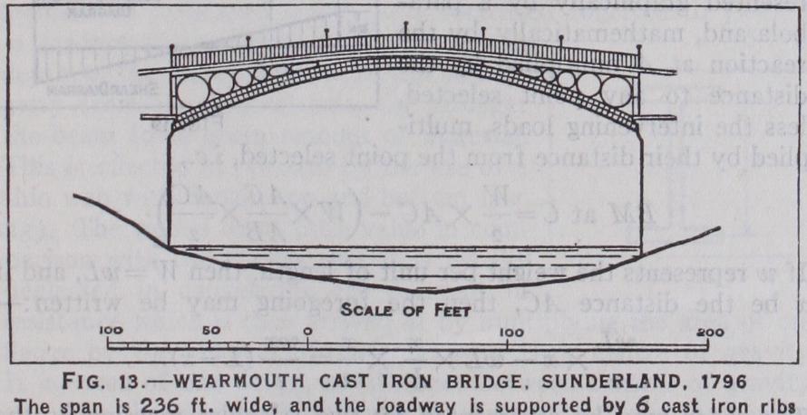
was greatly used in the past on account of its high compressive strength and resistance to corrosion, but its weakness in tension led to its abandonment. In compression a working stress of io tons per sq.in. is quite allowable on short struts, but in tension this has to be reduced to 2-1 tons per square inch. The Wearmouth bridge at Sunderland (fig. 13) was erected in 1796, and was one of the most daring structures ever erected in this material. It has a span of 236f t., and the roadway platform is supported by six cast iron ribs, each 5ft. deep but only 4in. wide. They were lightly braced together by cross-bracing and they safely carried the traffic. In 1859 Robert Stephenson inserted three wrought iron tubular ribs between each pair of cast iron ribs, and this composite structure is now being replaced by a steel arch of 3 7 5f t. span, but the original cast iron ribs are in perfect condition.
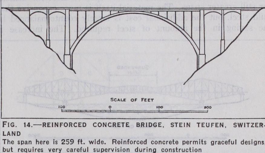
is a composite material of construction in which the compressive stresses in the members are taken up by the concrete, while in the parts subjected to tension or shear, mild steel sections (usually round rods) are inserted to resist the tensile or shearing stresses to which the concrete itself can only offer a poor resistance. Being a composite material, whose strength de pends upon the correct position of the steel reinforcement, it necessarily follows that, unless the work at the site is kept con stantly under observation, errors creep in. The working stresses allowed are 16,000lb. per sq.in. in tension in the steel, and 600lb. per sq.in. in compression in the concrete of a proportion of one part of Portland cement to two parts of sand to four parts of aggregate, none of the latter being large enough to be retained by a mesh a in. square (fig. 14).
The manufacture of this material as a reliable commercial product led to a great development in bridge construction about the middle of the last century, as it permitted the general adoption of types of bridges other than the arched.
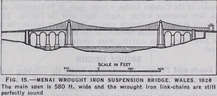
The usual working stresses are 5 tons per sq.in. in tension, 4 tons per sq.in. in compression in short struts, and 4 tons per sq.in. in shear. Wrought iron has a greater resistance to corrosion than mild steel, and there are numbers of bridges that were constructed in this material about 5o or 6o years ago that are still in good con dition. The Menai suspension bridge (fig. 15) was constructed over zoo years ago (1819-26), and apart from corrosion at one particular spot, the wrought iron links, of which its main chains are composed, are still perfectly sound.
led to another considerable advance, especially in the size of the spans that could be adopted economically. The working stresses allowed are 8 tons per sq.in. in tension, 61 tons per sq.in. in compression for short struts and 5 tons per sq.in. in shear. The working stresses in compression are usually based upon a formula that takes account of the column action in the member, a common form for compressive members with riveted end connections being 8 (I — •oo331) tons per sq.in., l being the length of the member in inches, and r its radius of gyration, also in inches. The ultimate breaking strength of mild steel is usually specified as not to vary outside the limits of 28 to 32 tons per sq.in. with an extension of 2o% in 8 inches. The chemical com position must be such that on analysis it must not show more than .o6% of sulphur or of phosphorus.
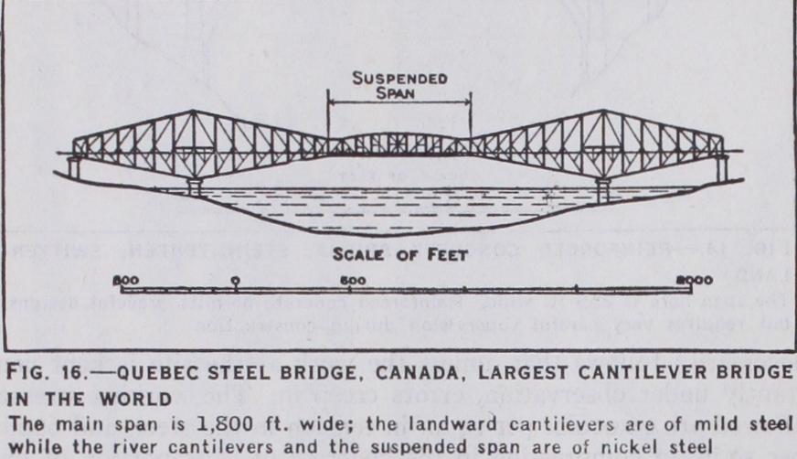
The Quebec bridge (fig. 16), with a span of i,800ft., is the largest cantilever bridge in existence and is an outstanding exam ple of a modern steel structure. It was opened in 1918 after the failure of one on the same site which collapsed in 1907 while being constructed. Misfortune dogged the second structure, as the suspended span fell as it was being erected, owing to faulty erection details, but the main structure was undamaged and a new suspended span was safely got into position. The river can tilevers and the suspended span were constructed of nickel steel.
has been developed to meet the demand for still greater spans. The material itself is more expensive than mild steel, but the additional cost is largely counterbalanced by the saving in the amount of steel required. The increase in strength beyond mild steel has been obtained either by increasing the proportion of carbon or by the introduction of nickel, chro mium or other metals. In the former case, the working stress has been raised to 9 tons per sq.in. in tension with a correspond ing increase in compression and shear. For alloy steels, such as nickel and silicon steels, the figure is 10.5 tons per square inch. As was mentioned, nickel steel was used in the suspended spans of Quebec bridge, while silicon steel was used in the stiffening trusses of the Camden bridge, 1,75oft. span, at Philadelphia, and the Bear mountain bridge, 1,632ft. span, over the Hudson. This material is also to be largely used in the Sydney bridge ribs of i,65oft. span. The main members of the Hell Gate arch (fig. 17) at New York, span t,oi7ft., were constructed of high carbon steel.