
COMPASS, a term of which the evolution of the various meanings is obscure; the general sense is "measure" or "measure ment," and the word is used thus in various derived meanings— area, boundary, circuit. It is also more particularly applied to a mathematical instrument ("pair of compasses") for measuring or for describing a circle, and to the mariner's compass.
The common mathematical compasses or dividers are composed of two legs or rods, usually of steel, joined together by a pivot joint at one end and pointed at the other. When used for drawing circles or arcs, the lower parts of the legs are removable or change able for a new section carrying pen or pencil. Beam compasses, which consist of points sliding on a bar, to which they may be clamped at any desired point, are used for lengths greater than the pivot compasses can expand. The compasses used in engi neering drawing are more fully described in the article DRAWING, ENGINEERING. It should be noted, however, that while the instru ments used in this work are simple in design careful manipulation must be exercised to obtain good results.
Proportional dividers or compasses have a point at each end of the leg and the pivot between, thus forming a double pair of compasses opposite to each other. To adapt these two sets of compasses for variable proportions, the pivot is made a clamping screw and may be fixed at any point, or contains some similar device. In one type of proportional divider the whole length of the legs is divided into 200 equal parts, which are further sub divided into tenths by means of a vernier. By this means any desired ratio may be readily set off. Such an instrument is ap plicable to a variety of purposes in connections with lines, planes and solids. For example, the ratio between the diameter and the circumference of a circle is quickly obtained by one setting of the vernier, the circumference being reduced to lineal measure. Tri angular compasses have three legs so that the vertices of a 4,i angle may be all transformed simultaneously. See also Tool,: Measurement.
The compass has long been used in land surveying as an instru ment for determining directions and, indirectly, angles. Almost all of the old surveys in America have been made with the com pass as the angle-measuring instrument, and while this instrument to a great extent has been supplanted by the transit there are still many compasses in use. The compass is frequently used in pre liminary mine surveys and for exploratory surveys, and the com pass on the transit instrument is always used in all but city sur veys as a check. A knowledge of the compass and compass sur veying is essential to a clear understanding of old surveys, with which every surveyor is concerned when resurveying old lands measured by compass survey. For these reasons, the compass and compass surveying finds a place in every treatise of survey ing and is discussed under the article SURVEYING. The solar com pass is an instrument for determining the true meridian by an observation on the sun. It was formerly specified for important government surveys in the United States.
There are two distinct types of mariner's compasses in general use at the present time—the magnetic compass, which depends , upon the Earth's magnetic field to obtain its directive force, and the gyro-compass (q.v.) which obtains its directive force from the Earth's rotation. (X.) The Magnetic Compass, with which this article is concerned, is an instrument by means of which the directive force of that great magnet, the Earth, upon a freely-suspended needle, is uti lized for a purpose essential to navigation. The needle is so mounted that it only moves freely in the horizontal plane, and therefore the horizontal component of the earth's force alone directs it. The direction assumed by the needle is not generally towards the geographical north but diverges towards the east or west of it, making a horizontal angle with the true meridian, called the magnetic variation or declination; amongst mariners this angle is known as the variation of the compass. In the usual navigable waters of the world the variation alters from 3o° to the east to 45° to the west of the geographical meridian, being westerly in the Atlantic and Indian oceans, easterly in the Pa cific. The vertical plane passing through the longitudinal axis of such a needle is known as the magnetic meridian. Following the first chart of lines of equal variation compiled by Edmund Halley in i7oo, charts of similar type have been published from time to time embodying recent observations and corrected for the secular change, thus providing seamen with values of the variation accurate to about 3o' of arc. Possessing these data, it is easy to ascertain by observation the effects of the iron in a ship in disturbing the compass, and it will be found for the most part in every vessel that the needle is deflected from the magnetic meridian by a horizontal angle called the deviation of the com pass; in some directions of the ship's head adding to the known variation of the place, in other directions subtracting from it. Local magnetic disturbance of the needle due to magnetic rocks is observed on land in all parts of the world, and in certain places extends to the land under the sea, affecting the compasses on board the ships passing over it. The general direction of these disturbances in the northern hemisphere is an attraction of the north-seeking end of the needle; in the southern hemisphere, it is repulsion. The approaches to Cossack, North Australia; Cape St. Francis, Labrador; the coasts of Madagascar and Iceland, are remarkable for such disturbance of the compass.

The compass as we know it is the result of the necessities of navigation which have increased from century to century. There are two main types of magnetic compass, the dry card and liquid compass; the former, known as the Thomson compass, invented by the late Lord Kelvin, is almost universally used in the merthitile marine but has been superseded in the British navy by the liquid type.
The Compass Card.—The card consists of a paper ring marked with degrees and points similar to that shown in fig. I. This is mounted on a frame, fig. 2, where an aluminium ring is connected by 32 radial silk threads to a central disc of minium; this is pierced in the centre to receive an aluminium cap with a highly polished phire centre worked to the form of an open cone. To direct the card eight short light needles are suspended by silk threads from the outer ring. The magnetic axis of any system of needles must exactly coincide with the axis passing through the north and south points of the card. Single needles are never used, two being the least number, and these are so arranged that the moment of inertia about every diameter of the card shall be the same. The combination of card, needles and cap is generally termed "the card"; on the continent of Europe it is called the "rose." The section of a compass bowl in fig. 3 shows the mounting of a Thomson card on its pivot, which, in common with the pivots of most other compasses, is made of brass, tipped with osmium-iridium, which although very hard can be sharply pointed and does not corrode. Fig. 3 shows the gen eral arrangement of mounting all compass cards in the bowl. In fig. 4 another form of compass called a liquid or spirit compass is shown partly in section. The card nearly floats in a bowl filled with distilled water, to which 35% of alcohol is added to pre vent freezing ; the bowl is hermet ically sealed with pure india rubber, and a corrugated expan sion chamber is attached to the bottom to allow for the expansion and contraction of the liquid. The card is a mica disk, either painted as in fig. 1, or covered with linen upon which the degrees and points are printed, the needles being en closed in brass.
After the outbreak of the World War, as a result of the neces sity of the situation, much pioneer work was done at the royal aircraft experimental station at Farnborough, and it was found that the main problems to be solved were (i.) to damp the vibra tions of the engine to such an extent that they had no effect on the compass, (ii.) to so design the card that the effect on it of change of speed and course, or both, was as small as possible.
Definitely to accomplish (i.), it was necessary to produce a suspension so efficient that the vibrations were practically ab sorbed before they reached the bowl, and at the same time the compass had to be definitely located.
The bedding of cotton waste and that of horse-hair were later replaced by varying combinations of springs and felt pads, until finally a very efficient suspension was found in Sorbo rubber, which has since been generally employed.
In modern types, provision is made for securing Sorbo pads to the inside of the container in such a manner that they absorb vibrations in a lateral and vertical direction, special means are also provided for locating the compass inside the container so as to avoid any displacement of the lubber point.
Problem No. (ii.) arises owing to the fact that the true vertical is replaced by a false vertical when changes of speed and course, or both, are made. In the space at disposal, it is impossible to explain the effect on the compass under all conditions, but exam ples are given of the effect of change of speed only and of change of course only, in order to give a general idea of the complications that may arise.
Assume the magnet system to be replaced by a single needle suspended from a point above its centre of gravity and that the aeroplane is steering E. and begins to increase speed. The needle lags behind and is W. of the pivot ; it will then swing to meet the line of dip through the pivot and settle there, producing easterly deviation. North and south accelerations have no effect because the line of the needle is not disturbed from the line of dip.
Supposing now a change of course from N. to E., the false vertical points down and W., the deviation is easterly as in the above case; if this deviation is less than the change of course, the compass underestimates the change; if the deviation is equal to the change of course, no turn is indicated at all; and if deviation exceeds the change, the sense of the turn as registered is opposite to the actual turn. The effect is the same turning from N. to W.
Turning from S. to either E. or W., the effect is to exaggerate the turn and is not therefore serious.
Turning from E. to W., there is no immediate effect, as the false vertical points down and N. or S. ; but the angle of banking brings the false vertical nearer, or further, from the line of dip, thus diminishing or increasing the directive force.
From the above it will be seen that the most serious trouble arises when course is altered from N. and is commonly called "northerly turning error." The above effects are the most important, but several others are introduced as well and may modify the former.
Development of the compasses was generally in the hands of the Admiralty compass department from the middle of 1917 onwards and proceeded fairly rapidly until finally, in 1918, the compass was produced. Up to this time the card, sisting of card, float, and .magnet system, was substantial, as, in ship compasses and when disturbed its oscillations were periodic.

Without a card, however, it was difficult to use this instrument as a compass, and to overcome this, two very novel methods were introduced. In the first, a graduated ring was fitted to the top of the compass bowl, capable of being rotated and clamped in any position ; grid wires were fitted across the inner diameter, running from o° to i8o°. To use this instrument as a compass, the ring is rotated until the course required is opposite the lubber point when it is clamped; the head of the machine is then brought round until the N. S. filament of the magnet system is parallel to the grid wires.
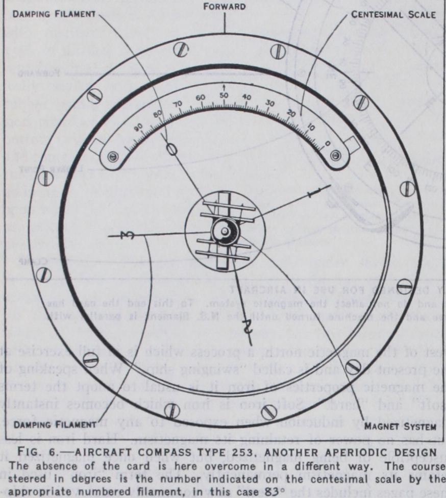
In the second methcd, a scale, graduated to ioo°, is secured to the inner side of the bowl, the centre of the scale being in fore and aft line. The damping filaments are numbered o, i, 2, 3 clockwise looking down at the compass and spaced as follows: ioo°, ioo°, ioo°, 6o°, making 36o° in all, and so secured to the cap that when the o filament coincides with the o on the scale the heading is North. Similarly with the No. i filament at 8o° the heading would be South or i8o°.
The fact that aeroplanes operate in extremes of temperature provides a further problem. Specifications for modern aeroplane compasses provide for a range of temperature from —5o° C to +5o°. Pure alcohol is the most suitable liquid and will not freeze at the low temperatures. Unfortunately, it has been very difficult to find any paint or other coating which will stand it, the result being discoloration of the liquid and the formation of deposits.
Figures 5 and 6 show two aperiodic compasses, the former fitted with graduated rotatable ring, grid wires and clamp, the latter with the centesimal scale. The courses indicated are respectively N.E. or 45° and 83° or N. 83° E.
Instead of observing the deviation solely for the purposes of correcting the indications of the compass when disturbed by the iron of the ship, the practice is to subject all deviations to mathematical analysis with a view to their mechanical correction. The whole of the deviations when the ship is upright may be expressed nearly by five coefficients, A, B, C, D, E. Of these A is a deviation constant in amount for every direction of the ship's head. B has reference to horizontal forces acting in a longitudinal direction in the ship, and caused partly by the per manent magnetism of hard iron, partly by vertical induction in vertical soft iron either before or abaft the compass. C has reference to forces acting in a transverse direction, and caused by hard iron. D is due to transient induction in horizontal soft iron, the direction of which passes continuously under or over the compass. E is due to transient induction in horizontal soft iron unsymmetrically placed with regard to the compass. When data of this character have been obtained the compass deviations may be mechanically corrected to within 0—always adhering to the principle that "like cures like." Thus the part of B caused by the permanent magnetism of hard iron must be corrected by permanent magnets horizontally placed in a fore and aft direction, the other part caused by vertical soft iron by means of bars of vertical soft iron, called Flinders bars, before or abaft the com pass. C is compensated by permanent magnets athwart-ships and horizontal; D by masses of soft iron on both sides of the compass, and generally in the form of cast-iron spheres, with their centres in the same horizontal plane as the needles; E is usually too small to require correction; A is fortunately rarely of any value, it is constant and can be adjusted by moving the lubber line in steering compasses. The deviation observed when the ship inclines to either side is due (I) to hard iron acting vertically upwards or downwards; (2) to vertical soft iron immediately below the compass; (3) to vertical induction in horizontal soft iron when inclined. To compensate (I), vertical magnets are used; (3) is partly corrected by the soft iron correctors of D ; (2) and the remaining part of (3) cannot be conveniently corrected for more than one geographical position at a time. Although a compass may thus be made practically correct for a given time and place, the magnetism of the ship is liable to changes on changing her geo graphical position, and especially so when steaming at right angles or nearly so to the magnetic meridian, for then sub-permanent magnetism is developed in the hull. Some vessels are more liable to become sub-permanently magnetized than others, and as no corrector has been found for this source of deviation the navigator must determine its amount by observation.
Every compass and corrector supplied to ships of the British navy and machines belonging to the air ministry is examined and tested at the admiralty compass observatory.
The director is responsible for investigating the magnetic char acter of ships, selecting suitable positions for the compasses in the early stages of design and subsequently keeping records of their behaviour; similarly, in the case of machines for the Air ministry, he advises during the mock-up stage.
See also MAGNETISM and NAVIGATIJN ; articles on Magnetism of Ships and Deviations of the Compass, Phil. Trans. (1839-83), Journal United Service Inst. (1859-89) , Trans. Inst. Nay. Archit. (186o-62) , Report of Brit. Assoc. (1862) , London Quarterly Rev. (1865) ; also Admiralty Manual (1862-192o) ; Towson's Practical Information on Deviations of the Compass (1886). (E. W. C.; G. B. H.)