
CONCRETE is a building material made by mixing stone, sand, water and a cementing material. The ingredients are mixed together with the addition of clean water into a plastic mass which gradually hardens into a rock-like substance of the nature of conglomerate. As a building material it is distinguished by the facility with which it can be deposited and moulded while plastic into almost any shape. Materials suitable for its manufacture are almost universally available and the mixing and placing do not require expert labour. It is adapted to an infinite variety of uses in engineering and architecture, including massive structures such as heavy foundations, retaining walls, dock walls, breakwaters, bridges and dams, and more intricate construction in ferro-con crete for floors, columns, buildings, arches, domes, towers, water tanks, pontoons, foundation cylinders, piles, open-work jetties and many other purposes. It has been used in masses of over 3o million cu.ft. in a single dam.
Concrete made with lime as the cementing material was largely used by the Romans in the construction of aqueducts, bridges and other massive work, generally with a facing of brickwork or masonry on the exposed surfaces, and some specimens of the ancient works have exhibited extraordinary durability. Lime in some form was almost the only binding material available until the introduction in the i9th century of Portland cement. The latter material is so superior in strength and reliability that it has almost superseded lime, except for unimportant work. Limited use is also made of other cements having qualities similar to Portland cement, such as natural cement and cement made from blast furnace slag (see CEMENT). When water is added to cement a slow chemical action takes place with liberation of some heat, and the cement in a few hours begins to harden into a stone-like substance. When it is mixed with sand a mortar is formed which sets hard, but with less ultimate strength than neat cement, and if broken stones are mixed with the mortar, concrete is obtained. In practice the materials are mixed together at one time and sound dense concrete is obtained when the mortar is in such volume and so mixed as to fill all the interstices among the broken stones. The sand used should be clean and sharp, entirely free from clay, loam, silt or vegetable matter, and it will give best results when it is a good blend of grains of all sizes from +in. down to T--61-0–ffinch. It may be obtained in a natural state from pit, river or seashore, or may be produced by crushing natural rock such as granite, trap or hard sandstone.
The stone may be pebbles or flints from gravel beds, or crushed hard rock, or broken artificial material such as slag, bricks, clinker or even concrete. Cinders and coke are sometimes used to form a light concrete, but should be excluded from important work. Hard limestone is generally suitable but has been found unsatisfactory in concrete conduits for conveyance of soft water, and is not the best material for producing fire-resisting concrete. Granite, gneiss, trap and hard sandstone rock produce good aggre gate for concrete. Generally the angular stones produced by crushing rock are less easily formed into dense concrete without voids than the rounded stones of natural gravel which slip past each other readily and are thus more easily compacted together. Smoothness of surface of the stones is no disadvantage from the point of view of adhesion of the materials when the stones are small. .The water used for mixing should be clean and free from acid alkali, oil or vegetable contamination. Sea water can be used without adverse effect other than the production of some surface efflorescence. Water from peat moors should not be used.
Concrete Mixtures.—Concrete may be mixed in very differ ent proportions adcording to the strength required, and the size of stone used may be varied in accordance with the massiveness of the rock. The general principle to be followed in proportion ing the mixture is that the volume of mortar produced by the mixing together of the cement and sand should be rather more than sufficient to fill the interstices of the broken stone so that no unfilled voids remain. The voids in broken stone are usually under 5o% so that a quantity of sand equal to half the broken stone will normally suffice for complete filling. Relative propor tions of cement, sand and stone, are frequently stated thus : 3 : 6, which indicates a mixture in the proportions of one part of cement to three parts of sand and six parts of stone. Such a mixture with stone of a maximum size of 3in. is suitable for foundations of mass concrete and similar work where great strength is not required. A : 2 : 4 mixture is generally appro priate for reinforced concrete building construction with stone not exceeding so that the concrete may be readily filled between and around the reinforcing bars. Mixtures still richer in cement are required for concrete piles to obtain adequate strength and for tanks and hydraulic structures to obtain water tightness. The richest mixture in common use is r : I : 2 which is suitable for reinforced concrete in marine works, and for reinforced conduits to convey water under pressure. The propor tions given are in round numbers, but the best proportions to use for particular materials should be determined by ascertaining by experiment the nature of the grading and the percentage of voids. The densest mixture of stones and sand, i.e., the one which weighs most per unit volume, will be capable of furnishing the strongest concrete. The tests for grading are used to indicate whether a part of the constituent materials should be augmented or dimin ished. Addition of fine sand to promote water-tightness is often useful in concrete for hydraulic and marine works. The propor tion of water to be used is almost as important as that of the other constituents. Enough water should be added to produce, after thorough mixing a plastic mass which can be rammed and tamped into position, so as to fill completely all corners and en close solidly all reinforcement where such occurs. Too dry a mix ture will give rise to inevitable voids and surface defects, while excess of water causes marked diminution of strength. Small quantities of concrete may be mixed by hand on a wooden plat form, the dry materials being turned over by shovel two or three times before water is added, and the mixture again turned over twice while wet or until a uniform consistency is obtained. Most concrete mixing is now done by machines, in quantities of from 6 cu.ft. to 6o cu.ft. at a time. In one type the mixing is done in a power-operated drum having internal vanes which cause rapid and thorough mixture of the materials as the drum rotates. The machine includes power-operated loading and discharging apparatus and a measuring tank for water.
The question of the endurance of concrete under exposure to chemicals is important. Sea water contains salts which sometimes penetrate and affect pervious concrete and any steel reinforcement contained therein. It is considered that magnesium sulphate is the most injurious of such salts. The fundamental precaution to be taken in the case of concrete for marine structures is to make the concrete so dense that penetration by water is pre vented. A mixture in the proportions i : i : 2 formed with well graded small aggregate and an adequate proportion of very fine material in the sand will give good endurance under most circum stances. Concrete is readily attacked by strong acids, but where thoroughly hardened and of dense quality it offers considerable resistance to weak acid solutions. In certain arid regions soluble alkaline salts contained in the ground are injurious to concrete. Such salts include the sulphates and chlorides of magnesium sodium and calcium. The remedy, as in the case of sea water appears to be the use of dense impervious concrete. Mineral oils such as petroleum, engine and transformer oils have little effect on good concrete. Vegetable oils, such as palm oil, have on the other hand a very injurious effect, as they unite with the lime of the cement and cause softening and disintegration.
Properties of Concrete.—The most important quality of concrete is the facility with which it can be formed into large and strong monolithic structures. Its usefulness depends on high compressive strength in conjunction with great durability and adequate tensile strength to ensure cohesion. The strength of concrete naturally depends on the quality and proportions of the constituents as well as the methods of mixing and placing, and obviously the proportion of cement used will have a large effect on the result. In England compressive strength is commonly de termined by the force required to crush 6in. cubes of concrete. In the United States 6in. by i 2in. cylinders are usually specified. When cement is used complying with the British Standard Specifi cation 1925, the crushing stress for cubes 28 days old should be not less than 2,000lb. per sq.in. for a i : 2 : 4 mixture, rising to 3,000lb. per sq.in. for a i : i : 2 mixture. Much higher results are commonly obtained. The tensile strength is only a fraction of the compressive strength, usually about one-tenth. Concrete expands and contracts with rise and fall of temperature and it is a curious and important fact that the rate of expansion is almost the same as that of steel, a condition which enables the two mate rials to act together in the structural combination known as ferro concrete, where primarily the concrete sustains the forces of com pression and the steel resists the forces of tension. The question of the elasticity of concrete is important in relation to the stresses in ferro-concrete construction. Concrete yields much more than steel under the same stress, so that relatively the concrete is more elastic to an extent which for convenience is e7pressed by a ratio termed the modulus ratio. The actual ratio for matured concrete is commonly from 7 to r o, whereas for purposes of cal culation a ratio of i 5 is often assumed. While undergoing the chemical changes that transform it from a plastic to a hard mate rial, concrete is subject to shrinkage, which, while introducing some secondary stresses in the materials of ferro-concrete, causes it to close around and hold the reinforcing bars with firm grip. Watertightness is of special importance in hydraulic and marine structures and is promoted by having a mixture in which the mor tar is rather more than sufficient to fill the interstices in the aggre gate and is watertight in itself. As a rule watertightness cannot be relied on where the mortar is a i : 2 mixture, whereas a i : i mixture will usually be satisfactory. Proper grading of the sand and a sufficiency of fine sand are necessary for the attainment of the best results.
Concrete is largely used as a casing around structural steel work for protection against fire. It is well known that bare steel work, owing to its excellent heat conducting properties, soon attains a dangerous temperature in a fire with consequent failure from softening. Concrete in comparison with steel is a poor conductor of heat and furnishes protection by delaying the pas sage of heat to the steelwork. As the temperature of the concrete rises on the surface to a high level dehydration takes place, accom panied by increase in the heat insulating properties, so that although the surface layers of the concrete are damaged the pen etration of heat is thereby further hindered. A thickness of tin. of concrete well bound to the steelwork with wire or metal mesh reinforcement meets the requirements of certain building author ities and fire associations. Concrete is frequently used as the wearing surface on floors subject to foot traffic and occasionally also to floors to sustain wheeled traffic. The wearing surface is usually a coating of fine concrete or mortar from i to tin. thick applied on top of the concrete floor. The requirements of such a coating are strength and resistance to abrasion, as well as good adhesion to the concrete below, and they are in the main to be attained by the use of fine hard aggregate such as quartz, granite or flint, in a well graded mixture from fin. down to fine sand. Two parts of such aggregate mixed with one part of cement, applied before the floor concrete has completely set, and well trowelled to produce a smooth surface, should produce a satisfactory result. Carborundum offers very high resistance to abrasion and in a finely divided form like fine sand is sometimes mixed with the surface floor layer. Small proportions of powdered cast-iron or steel are also sometimes used to improve the density and wearing qualities of floors, but it is doubtful whether they add anything to the wearing properties of good concrete made with quartz or granite. Silicate of soda is an acid-resisting liquid chemical "hardener" which may be added to the mixing water or applied on the surface of finished concrete, with the object of hardening the surface and improving the resistance to abrasion.

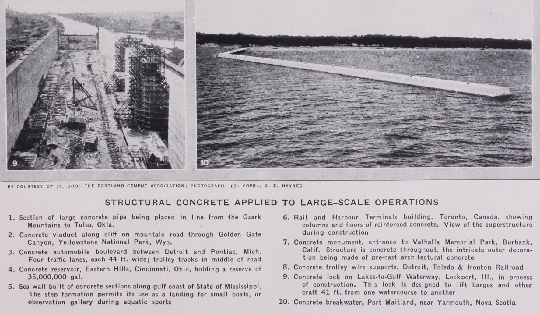
Dams, dock walls and graving docks are classes of structure in which concrete is used in enormous masses and where cyclopean concrete may often be used to advantage. In the case of a dam, various classes of concrete are used to suit the conditions in dif ferent parts of the work. In the heart of the dam, mass and weight are required, and proportions varying from i : 2 : 4 to I : 3 : 6 are commonly used. Watertightness is obtained by pro viding a richer and denser layer next to the water face with a mixture varying from i : i : 2 to i : 2 : 4. In the case of a high dam large compressive stresses will be developed in the concrete near the inner and outer surfaces at the bottom under varying conditions of water level, so that richer and stronger concrete may be necessary in these regions. Where climatic conditions are severe rich concrete may be necessary on all exposed surfaces and sometimes it is advisable to have the surfaces protected with a facing of granite or other durable masonry. Somewhat similar conditions obtain in the case of concrete for dock walls and graving docks. The construction should be watertight and sur faces exposed to wear and abrasion should be protected either by rich concrete or by a separate facing of granite or similar material. A number of dock walls have been provided with foundations in an interesting manner by sinking large cellular structures of con crete through the ground until a firm foundation is reached. Such constructions are known variously as caissons or monoliths and are usually built up on a metal shoe formed with cutting edges. The sinking is effected by excavating the earth from the cellular interior spaces by hand excavation or by mechanical means, using a grab. As excavation proceeds the structure sinks and at the same time building upwards with mass concrete or concrete blocks takes place so that the top is kept above ground level. When a firm foundation has been reached the interior spaces may be filled with concrete or the bottom may simply be plugged with concrete and the rest of the spaces filled with sand or broken stone. Such a foundation structure is generally used as a base on which to build a wall of mass concrete. In the case of breakwaters (q.v.) very large use has been made of concrete in the form of huge pre-cast blocks. Where the depth of water is not great the whole structure may be formed of such blocks, but more frequently their use is confined to the upper part of the construction resting on top of a broad bank of rubble deposited in the water. The blocks are made and cured in a large construction yard ashore and are handled and lowered into position by heavy travelling cranes and set into cor rect position by the aid of divers. At the port of Dublin, blocks of 35o tons weight were used which were handled and deposited by heavy floating sheers.
Beams.—Beams of plain rectangular form are frequently used as lintels bridging over openings in walls, and are usually formed of the same thickness as the wall and with a depth arranged to suit the load. The tensile flange is constituted by a number of rods in the bottom of the beam while an area of concrete in the top of the beam constitutes the compression flange as shown in fig. 4. Reinforcement of vertical "stirrups" or other form may be provided to aid the concrete in re sisting shearing stresses. Beams in rein forced construction are most frequently required to carry reinforced concrete floor slabs which when cast integrally with the beams can be utilized to augment their cross section and strength. Such a beam is indicated in fig. 5. In this case the concrete in the vertical stem or web is called upon to sustain proportionately larger stresses so that web reinforcement may become essential, and this is provided either by vertical links or "stirrups" as shown, or by bending up in a diagonal direction certain of the main tension rods in the end portions of the beam, or by a combination of the two methods. Suitable arrangements for continuity may be pro vided, as shown in fig. 2, which represents a beam continuous over two spans. It is noteworthy that by bending up certain of the main rods and overlapping them in the top of the beam over a support not only is provision made for resisting shearing stresses but also for withstanding the reverse bending which occurs. Con tinuous beams are usually more heavily stressed at intermediate supports than in the central por tions of spans so that it is often appropriate to increase the depth by forming the bottom with a downward slope for a short dis tance next to each support.
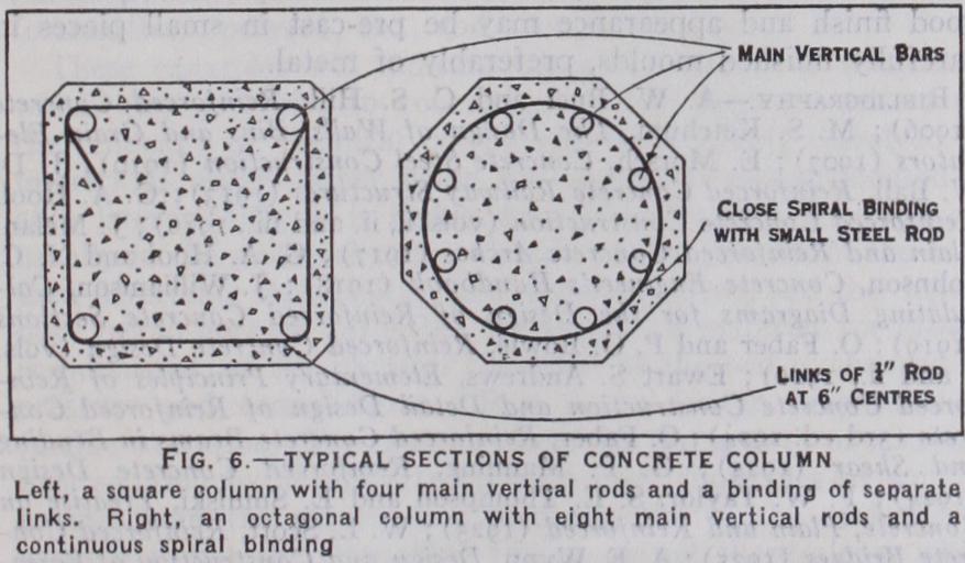
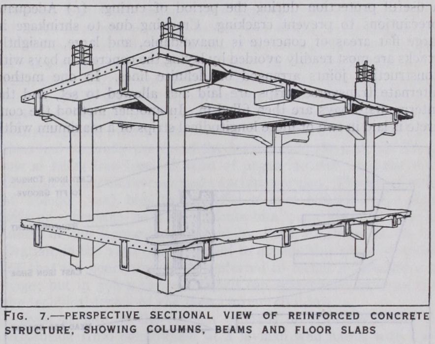
Columns.—A ferro-concrete column for the support of vertical loads, when properly designed and constructed, is at once econom ical. durable and fire resisting. It consists of a shaft of concrete containing a number of vertical steel bars bound together at close intervals by smaller steel bars either in the form of a continuous spiral or of separate links. The shaft may have any shape appro priate to the conditions and site. Sections of circular or octagonal shape are commonly adopted when spiral hooping is used, while square and rectangular cross sections are more commonly used with a binding of separate links. Typical cross sections of a square and an octagonal column are shown in fig. 6. The square column has four main vertical rods with a binding of separate links while the octagonal column has eight main rods with a continuous spiral binding. The thickness of concrete covering the main rods should in no case be less than i4in. The load is borne partly by the concrete and partly by the steel, the greater portion being usually allocated to the concrete. The distribution of the load takes place in accordance with the elastic properties of the materials, so that if the modular ratio (referred to above) is 15, each square inch of cross section of main steel rod will bear 15 times as much load as a square inch of concrete. Thus if the cross section of a particular column had 30o sq.in. of concrete and io sq.in. of steel, the steel would carry as much as 10 x 15 = 150 sq.in. of concrete and would therefore carry half as much as the actual concrete or one-third of the total load. If the average working stress on such a column were fixed at 5oolb. per sq.in. the capacity of the column for sus taining load would be ascertained thus:— It is seldom possible to arrange that columns shall be loaded uniformly over their cross section in the manner assumed in the foregoing simple calculation. In actual building construction they are usually employed to support ferro-concrete floors in a mono lithic construction whereby the bending of the floor beams induces bending effects also in the columns, which must be taken into con sideration along with the loads in determining the cross sections required. Fig. 7 is a perspective section showing a typical con struction in a building where the columns support main beams which in turn carry a series of subsidiary beams over which a slab floor is formed. It is readily understood that considerable labour is involved in fabricating and supporting the moulds for the beams in a construction of this type, and efforts at simplification have resulted in patented floors of the flat slab type in which all beams projecting below the floor slab are dispensed with and a thicker floor slab is supported directly on the columns through large cir cular or square capitals. Such a floor is usually reinforced by several systems of rods radiating from the columns and disposed near the under surface of the slab in the central portions of floor panels and near the top where they pass over the capitals. The design of floors of this type is based on approximate theory con trolled by the results of stress measurements in tests of actual floors. The method has hitherto found little application in Britain, where much more use has been made of light flat-ceilinged floors having in their lower part rows of hollow tile blocks set so as to leave intermediate spaces for the formation of narrow reinforced beams, the floor being completed by a continuous concrete layer placed over the tiles and beams. Floors of this type are well adapted for filling in the panels between the main floor beams of structural steel-framed buildings, and have the advantages of lightness and good insulating qualities, while a plaster ceiling can he applied to the grooved soffits of the tiles.
Foundations.—Reinforced concrete construction is adapted to varied uses in foundation work. Thus, retaining walls of ample strength can be readily constructed in places where there is no room for a wall of mass concrete. Heavy columns can be sup ported in a relatively thin but wide-spread foundation of reinforced concrete with great saving in weight, volume and depth of con struction, as compared with mass concrete. On weak ground, a complete layer of light reinforced concrete in the shape of a plain or ribbed slab may be provided to distribute the entire load over the whole basement area of a structure in an economical and effi cient manner unattainable with other methods of construction.
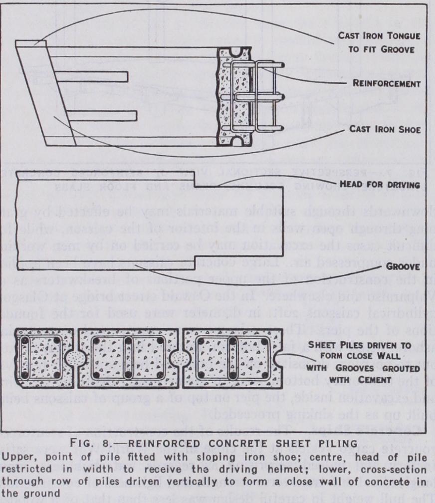
Ferro-concrete piles have largely superseded timber piles as a means of transmitting heavy loads down through layers of weak material to a firm stratum of ground, without the necessity for deep excavation. They are usually made of one or other of the types of column section shown in fig. 6, and are manufactured in a horizontal position in moulds laid out on a prepared floor. A fine concrete mixture of the order of : : 3 is desirable for piles, to enable them to withstand the severe stresses produced in handling and driving with a heavy hammer, and a still richer mixture is of advantage for marine work. When ordinary Port land cement is used piles will normally be fit for driving in 3o days; if first quality rapid hardening Portland cement is used the piles may be driven at seven days, and with the use of "ciment fondu" they may be driven when 24 hours old. Concrete piles require to be driven with a heavy hammer which for satisfactory results should weigh at least half as much as the pile. A steel helmet or collar fitted over the head of the pile receives the strokes of the hammer and transmits them to the pile head through a cushioning layer of canvas or rope. Fig. 8 shows the method of pile driving in progress for the foundations of a large power station where 6,000 concrete piles from 25ft. to 46ft. long were used. A close wall of piling driven from the surface can be readily pro vided in soft or wet ground in many cases where the construction of an ordinary wall within a deep timbered trench would be prohibitive owing to excessive difficulty and cost. The special piles used for such work are known as "sheet piles" and are formed with bevelled points and grooved ends so that they drive close together in a regular line. A satisfactory form has semi-circular grooves at each end and a short projecting tongue on the cast-iron point which engages with the groove on the last driven pile, while the upper end may be held to line between timber walings during the driving. The circular hole formed by the grooves of the meet ing piles is filled with cement mortar after being cleaned out with a water jet. This type of pile is shown in fig. 8 which also indi cates the restricted driving head which is provided to enable the driving helmet to pass the last driven pile.
Hydraulic Works.—There has been rapid extension in the use of ferro-concrete in all classes of hydraulic construction (see AQUEDUCTS and DAMS). It is employed for all classes of tank con struction, including underground covered tanks, tanks erected on the ground and tanks supported on high towers. For the latter class a circular form is usually most appropriate with circumferential hoop reinforcement to resist the bursting effect of the water pres sure on the sides. Where water pressure has to be resisted a rich concrete mixture not leaner than 1 : 14 : 3 is called for, and an in ternal rendering of cement mortar will give added security against percolation. It is also of great importance that the risk of forma tion of cracks should be eliminated as far as practicable, and con sideration of the elastic co-operation of the materials and the de sirability of keeping the actual tensile stress on the concrete below its rupture value lead to the employment of low tensile stresses on the steel. Satisfactory results may be expected when the sections of concrete and steel are suitably proportioned and the stress on the steel, when the latter is considered as taking the whole of the tension, is limited to about Io,000lb. per sq.in. The reinforcement must be consistently proportioned throughout and be without sudden breaks in the quantity or arrangement. Surfaces of con crete do not lend themselves very readily to satisfactory archi tectural treatment, so that in many fine buildings the supporting framework of reinforced concrete is entirely hidden behind face work of masonry or other material. Good effects in `buildings can be attained when the visible concrete is well finished and confined to well-proportioned and suitably lined vertical and horizontal bands of the framework, the rest of the elevation being formed of panelling and face-work of other materials. In bridges principal reliance must be placed on satisfactory form and proportions corn bined with very careful work in constructing and setting the moulds which form the exposed surfaces. Parapets and pillars of good finish and appearance may be pre-cast in small pieces in carefully finished moulds, preferably of metal.