
CONDENSER (ELECTRICAL), a piece of electrical apparatus used originally solely for storing an electric charge, but now having many forms and diverse industrial and scientific applications. Until comparatively recent years the term con denser has been associated almost exclusively with the leyden jar, although the name was not used until some time after the discovery of the jar. It was first bestowed by Alessandro Volta 2 7) upon a different apparatus used by him in the course of his investigations upon atmospheric electricity. Volta's apparatus more resembled an electrophorus (q.v.), and was used as a condenser of variable capacity. At that time electricity was regarded as a fluid which could be condensed if the proper pro cedure were adopted, but it is now known that the action of a condenser is to store electricity by an accumulation of charges on the plates, electrodes, or armatures of the condenser.
The electrical condenser is distinct in its properties from other electrical apparatus in that energy is stored in it in electrical form, and the energy which is passed into it during the charging process by connecting the condenser to a source of electromotive force is entirely or almost entirely returned again, when the condenser is discharged by connecting its plates or coatings by a wire. In the early days of electrical experiment in the 17th and i8th cen turies many attempts were made to store up the "electric fire." Leyden Jar.—The first real success in this direction was achieved by the discovery of the device subsequently called the leyden jar. This discovery was first made in October 1745 by Dean E. G. von Kleist of the cathedral of Kamin, who used a small apothecary's vial with a nail or piece of wire to make con nection inside, the vial being held in the hand. By presenting the nail to the conductor of an electrical machine he found that the electricity passed into the vial as he showed by taking it into another room where it was possible to set fire to spirits of wine with the discharge spark, and to receive a shock by touching the nail. Some three months later, in Jan. 1746, Pieter van Mussch enbroek, a professor in the University of Leyden, independently discovered the same phenomenon using a glass bottle filled with water and having an iron wire dipping into the water and pro jecting out through the cork so that it could be hung from a musket barrel suspended horizontally by silk threads. After elec trifying the bottle, a violent shock could be obtained if the mus ket barrel and the jar were simultaneously grasped.

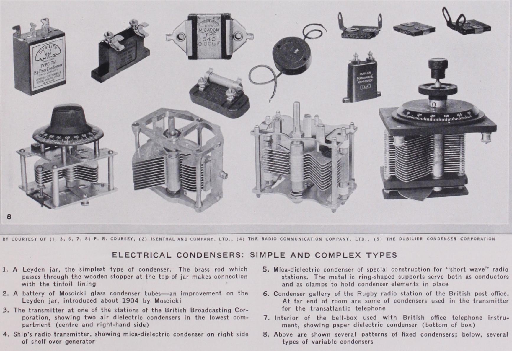
The leyden jar was in the succeeding years developed into various forms and put to many uses, both for purposes of science and amusement ; and it is still used in laboratories, though the interest in it is largely historical. For many electrical experi mental applications it forms a useful condenser which is not costly, but for most industrial applications it has been super seded by other forms of condenser having greater efficiency and other desirable electrical properties. The leyden jar of to-day consists of a wide mouthed jar or bottle of good quality glass, as free as possible from bubbles or other irregularities and coated inside and outside with a layer of tinfoil extending over the bot tom of the jar and for a distance up the side of one-half to two thirds of the height of the jar (P1. I. fig. I). The exposed upper surface is generally coated with shellac or similar varnish to re duce surface leakage. The top of the jar is usually closed with a wooden stopper through which a brass rod is passed to make connection with the tinfoil. Various sizes of jars are in use, these giving different electrical capacity values—the electrical capacity of a condenser being the measure of its electrical size or, in other words, the measure of the charge it can store under the appli cation of a given charging voltage.
The first mentioned of these properties, specific inductive ca pacity, determines the capacity of a condenser of given physical dimensions. It is expressed as the ratio of the capacity of a con denser having the particular material as dielectric to the capacity of the same condenser, or of a condenser of exactly similar physi cal dimensions but having the plates separated by air only. The higher the value of this constant, therefore, the greater is the capacity of a condenser of given dimensions. The materials giv ing high values for the dielectric constant have, however, in many cases other harmful properties which prohibit their practical use in condensers. Most useful condenser dielectrics have a dielectric constant below 8, while insulating oil, and oil- or wax-impregnated paper dielectrics have values usually between 2 and 4.
The second property—dielectric strength—expresses the abil ity of a condenser to withstand the application to it of high voltages. When the voltage applied between the plates of a con denser is gradually increased the electric stress in the dielectric is increased also, until ultimately a value is reached at which the dielectric gives way—or breakdown occurs—and a discharge, gen erally in the form of a spark, passes through the material. The breakdown voltage per unit thickness of the material depends to some extent upon the thickness itself and upon the nature of the conducting electrodes that are applied to its surfaces. In general the breakdown voltage is relatively greater for the thinner sheets of the material, with the result that it is generally economical to subdivide high voltage condensers into a number of smaller ele ments, connected electrically in series, each element having a thinner dielectric adapted to withstand the appropriate fraction of the total voltage applied to the whole composite condenser.
The resistivity of the dielectric expresses a measure of the leak age or passage of electricity from one terminal to the other when voltage is applied. The property is of most interest for condensers which are subjected to steady or direct voltages. It is a quantity which is most commonly measured in connection with condenser dielectrics as a means of estimating the quality of the dielectric, not only from the point of view of the quality of the material itself but chiefly as a guide to the efficiency with which it has been freed from moisture. Minute traces of water, whether in the form of moisture condensed on the surfaces of the dielectric or actually absorbed into the pores of the material, bring about a very marked reduction of the resistivity, and such reduction is generally ac companied also by a marked decrease in the breakdown voltage, or dielectric strength of the substance.
The dielectric phase difference is a property which is encount ered only when a condenser is subjected to alternating voltages, and it then expresses the departure of the condenser from the ideal. When a condenser is subjected to an alternating voltage there is a charging current flowing into it during all the time that the voltage across its terminals is increasing. This charging current falls to zero when the voltage reaches its maximum value, and dur ing all the time that the voltage is decreasing a discharge current will flow out of the condenser, this falling to zero again when the voltage reaches its minimum value and is about to commence in creasing again. Thus, if the applied voltage waveform is sinusoi dal, the waveform of the current flowing in the circuit—made up of the successive charging and discharging currents—will like wise be sinusoidal, but there will be a phase displacement between the two, the current wave being 9o° in advance of the voltage wave. In a condenser with an ideal or perfect dielectric—if such could be constructed—this phase displacement would be exactly 9o° and no energy would be expended in the dielectric ; but in all practical dielectrics a phenomenon known as electric absorption is observed, the effect of which is that the charging current does not cease at the instant that the voltage reaches a steady value, but persists for some time after in the form of a gradually de creasing absorption current. Likewise the discharge from most dielectrics does not cease immediately the applied voltage has been removed or has decreased to its steady minimum value, but it persists in the form of a gradually decreasing absorption dis charge. Thus the zero points of the current waveform of the con denser subjected to an alternating voltage do not coincide in time with the instants of maximum and minimum value of the voltage waveform, but are delayed by a small fraction of a period. The phase displacement between current and voltage is thus very slightly less than 9o°. The departure from exactly 9o° is the please difference. The amount of energy expended in the dielectric is directly proportional to the sine of this phase difference angle— or, since in almost all cases this difference is small, the losses be come directly proportional to the phase difference itself. This quantity is sometimes also expressed as the power factor of the dielectric (numerically equal to the sine of the phase difference, or the cosine of the phase angle).
For many condenser dielectrics the phase difference increases with frequency, with the result that condensers employing these substances are unsuited for use in high frequency circuits. With some other materials, however, the increase is either small or neg ligible while in some a maximum value is reached in the ordinary range of practical frequencies so that there is relatively a reduc tion of losses at the higher or radio frequencies. This property is one which has a very considerable bearing upon the choice of condenser dielectric for any given use, since in practice so many condensers are required for use in alternating current circuits either of high or low frequency.
The chief practical uses to which the early Leyden jars were applied was in conjunction with wireless telegraphy apparatus, and a modification of the original jars is still occasionally used for such purposes. An improvement was introduced about i9o4 by Moscicki in the form of elongated glass tubes (Pl. I, fig. 2) with silvered coatings for the conductors, and a thickening of the glass adjacent to the edges of the metal coatings so as to reduce the in tensity of the electric stress in the material at these points, arxd so to reduce the liability to breakdown, For ships' wireless trans mitting sets another modification has been much used. This con sists of interleaved glass and metal sheets mounted in an oil-filled container. The glass dielectric of these condensers has not incon siderable dielectric losses, when subjected to high voltages. The general growth in the power of wireless stations of recent years, accompanied by the replacement in many cases of the "spark" or damped-wave transmitters by continuous-wave ones, has rendered it imperative to make use of condenser dielectrics having the low est possible electrical losses. In some cases air dielectric con densers have certain advantages for radio uses, particularly for the short wave-length stations. They are, however, also used sometimes in the longer wave stations (Pl. I. fig. 3), where bulk is of no particular importance.
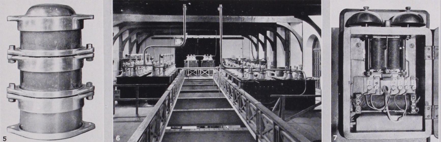
Mica as a dielectric for condensers for radio transmitters has been particularly developed during the last decade, apart from the use of smaller condensers for ship spark transmitters (Pl. I. fig. 4)• With it it has become possible to construct condensers for use in high frequency circuits wherein they often have to pass very large high frequency currents produced by valve oscillators, the condensers causing an energy loss of not more than o.o2% of the reactive kilovoltamperes flowing in the circuit. The electrical effi ciency of such condensers can thus be said to exceed 99.98%. For radio transmitters using frequencies in excess of about 2,000 kilo cycles quite small condensers with mica dielectric suffice, such for example as the small condenser shown in Pl. I. fig. 5, which is much used particularly for portable radio stations for military and simi lar purposes. At the other end of the scale are the huge condensers used in high-power radio stations, where very large currents and high voltages are involved. The photograph reproduced as Pl. I. fig. 6, of the condenser gallery at the Rugby Radio station of the British Post Office illustrates the use of a number of condensers of this type. On this gallery are grouped the condensers for the main oscillation circuit of the high-power telegraph transmitter of the station, these being disposed in two main groups on opposite sides of the gallery. At the far end are some of the condensers used in the transmitter for the Transatlantic telephone which is also housed in the same building.
These condensers are all constructed of a very large number of small condenser elements arranged in groups connected together in series and parallel to provide sufficient bulk of dielectric for the electrical loading. Each of these elements consists of inter leaved thin sheets of mica and metallic foil—usually copper or tin—securely held together to prevent relative movement. Each of these elements, therefore, has to support only a fraction of the total voltage applied to the condenser, depending upon the num ber of such elements connected in series; while likewise it has to carry only a fraction of the total current flowing into the con denser, depending upon the number of such elements connected in parallel. In the larger condenser illustrated in Pl. I. fig. 6, it may be seen that each of the radial arms or spokes of the ring-shaped supports consists of a number of such series-connected mica di electric condenser elements, and that all these arms or spokes are connected in parallel, this arrangement serving also as a means of supporting the central high voltage connection to the condenser, the other terminal being joined to these metallic ring-shaped sup ports, which serve both as conductors and as clamps for holding the condenser elements in position.
In the application of condensers to radio apparatus operating upon the very high frequencies necessary for "short wave" and "beam" transmissions, further difficulties have been encountered owing to the energy losses in the dielectric forming the terminal insulators for the condenser. The proper subdivision of the cur rent in the interior of the condenser to ensure that no part of the condenser is overloaded also presents some difficulty unless great care is taken to ensure that all the current paths through the con denser have as nearly as possible the same inductance. In con densers for long wave-length radio circuits this factor is of little importance, but with frequencies in excess of a few million per second excessive heating of parts of the condenser may occur if it is not considered in the design of the condenser. A recent form of condenser, with a mica dielectric, specially produced for use in these very high frequency circuits, is illustrated in Pl. I. fig. 5. It consists, as may be seen from the photograph, of several small con densers mounted upon one another, so that they are all joined in series. Each is enclosed in an insulating tube, which provides the insulation between the top and bottom metal parts which form the terminals of the condenser. The electrical stress in this in sulator is by this means reduced to a reasonably small figure, while inside each of the condenser parts the current flow is subdivided into several channels each con.sisting of a number of condenser elements connected in series, as requisite for the operating voltage and frequency.
So in radio transmitters and in receiving sets as now commonly used for the reception of broadcast transmissions, a variety of condenser arrangements is commonly employed. A group of such condensers is illustrated in Pl. I. fig. 8. In the upper part of this photograph are shown some patterns of fixed condensers, and in the lower part some types of variable air condensers as used for tuning the circuits of the receiver. Of the fixed condensers those of smallest capacity—below about o.oi microfarad—are custom arily made with a mica dielectric, while for the larger capacities paper dielectric condensers are generally used. Still larger capac ity condensers of similar type, up to about 20 microfarads, are used in the filter circuits of the so-called "battery eliminators" which are often used to enable a radio receiver to obtain its cur rent supplies from electric lighting mains, in which application they perform the functions of providing a low impedance bypass path for unwanted currents of audio frequency.
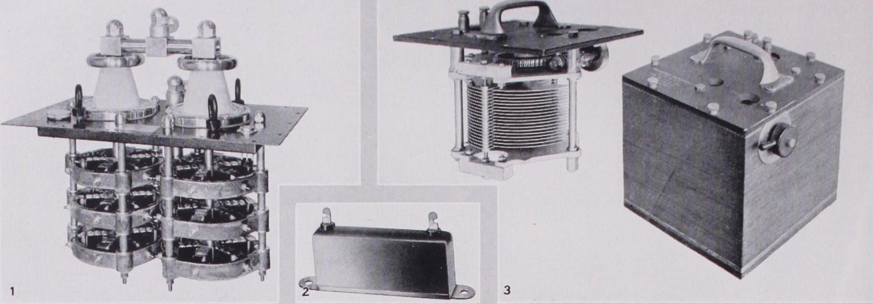
Variable condensers used in radio receiving sets are constructed in as simple a manner as possible in order to avoid unnecessary expense in their manufacture. Several patterns are illustrated in Pl. II. fig. and fig. 2. They are now almost always of the rotary vane type in which a number of fixed metal vanes are mounted on a supporting framework and a similar set of slightly smaller vanes are mounted upon a spindle carried in the same framework, so that by turning the spindle the one set of vanes can be moved so as to interleave with the other set to a greater or less extent. In these condensers the dielectric is the air between the two sets of plates; and some form of insulation is provided, so that although both sets of vanes are supported by the same framework they are electrically insulated from one another. The capacity of these condensers is almost directly proportional to the amount by which the two sets of vanes overlap one another, so that if the rotary set of vanes is semicircular the capacity of the condenser will be very closely proportional to the angular rotation of the spindle from its initial or "zero" position. Until recently all variable condensers were constructed of this form, the differences in design consisting mainly in the means adopted to support the various parts and to insulate the two sets of vanes; in recent years, however, other variations have been introduced primarily in order to facilitate the tuning of the circuits of the radio receiver in which the con densers are used. By appropriate shaping of the vanes of the con denser the capacity can be made proportional to the square of the angular rotation of the spindle, or to the reciprocal of the square of the angle, or to the logarithm of it, or to almost any other desired mathematical function. The object of such modifications is to facilitate the use of the apparatus by making the scale reading of the dial attached to the condenser spindle propor tional, for example, to the resonance wave-length of the circuit in which the condenser is used, or proportional to its frequency, etc. A typical form taken by a laboratory variable condenser is depicted in P1. II. fig. 3. Such condensers for accurate experi mental work need to be constructed in a much more robust man ner and on a larger scale than are those used in radio receivers. The most mechanically robust patterns can also be used as ca pacity standards for testing and measurement purposes, when they have been accurately calibrated. In some cases the space between the plates is filled with insulating oil to increase the capacity of the condenser.
Paper as a dielectric for electrical condensers has been used for many years, condensers using large sheets of this material, soaked in paraffin wax and interleaved with tinfoil sheets, having been employed since the early days of both telegraphic and telephonic communication. With the increasing use of telephones—every instrument usually requires at least one condenser (P1. I. fig. 7), and the exchanges large numbers—the methods of manufacturing these condensers have been very much simplified. To-day they are made by rolling long strips of paper and foil together on a machine until the required capacity is obtained, the con denser "plate" thus obtained being pressed flat and impregnated with some form of insulating wax. Various grades of paper are employed, depending to some extent upon the uses for which the condensers are intended, while for the conducting "plates" of the condenser either very thin tinfoil or aluminium foil is used, or a foiled paper, viz., a thin paper into the substance of which a deposit of tin is pressed to form a conducting coating. This latter conductor was introduced in 190o by G. F. Mansbridge at a time when the manufacture of long strips of tinfoil of sufficient thin ness for use in paper condensers presented almost insuperable difficulties. The condenser plates, after the impregnation, are sealed into a metal or insulating casing which must also prevent the access of moist air to the condenser paper, since this would cause rapid deterioration of the insulation.
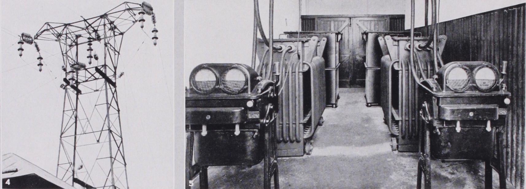
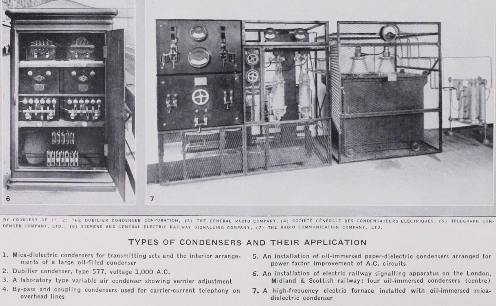
Condensers of this type, constructed with a type of paper that allows only of low electrical losses, are used on alternating cur rent electric power circuits for improvement of the power factor of the circuit. Particularly for voltages of about Soo and upwards similar condensers are often treated with an oil impregnation in place of wax, and are sealed in a metal tank or container filled with a high flash-point insulating oil (Pl. II. fig. 5). The oil being fluid permits of the flow of convection currents if any appreciable heat is liberated in the condenser, and so aids in the cooling of the condenser and tends to prevent failure of the dielectric. These condensers have also found application in conjunction with elec tric railway signalling equipment where they provide a means of resonating the circuits of the signalling relays (P1. II. fig. 6). For the electric induction furnace, too, these condensers are also used to form a resonant circuit tuned to the frequency of the generator supplying the electrical energy to the furnace, the winding of the furnace coil providing the inductance of the circuit, so that the requisite large current can flow through the circuit of the coil and condenser while the generator has only to provide the energy re quired to melt the metal in the furnace, the electrical losses in the condenser being negligible. These furnaces are commonly worked with alternator supply, at frequencies of between Soo and 5,000 cycles. Under these conditions the electrical losses in the con densers, if of paper dielectric, become of importance unless ade quate cooling of the dielectric is provided by the oil. For still higher frequencies, valve oscillators are often used, usually with mica dielectric condensers immersed in oil (Pl. II. fig. 7) .
The readiness of a condenser to allow the passage of high fre quency currents has furnished two other important applications of condensers in conjunction with high voltage electric power lines. When these lines are carried overhead they are liable to disturbances due to lightning and similar atmospheric electrical effects, which often cause damage to the transformers and other apparatus connected to the lines. With condensers connected be tween the lines and earth the high frequency disturbances and surges can be drained away to earth and their harmful energy dis sipated. Similar condensers joined to the lines and connected to a special type of radiotelephone apparatusprovide a means of guid ing speech communication along the power lines (Pl. II. fig. 4), and thus furnishing a valuable and very reliable means of com munication between the power- and sub-stations connected with the power line network. This communication is not so liable to in terruption and other disturbances as are separate telephone lines of the ordinary type.
In all these and many other applications of condensers the real heart of the condenser is the dielectric, and a proper use of the materials and knowledge of their properties has been the only means of building up the present known types of condensers. Many insulating materials besides those mentioned here are known, and may yet be applied in condenser construction as appro priate uses for them develop.
See P. R. Coursey, Electrical Condensers, their Construction, Design and Industrial Uses (1927), for extensive bibliography. (P. R. C.)