
DAMS. From immemorial times dams have been constructed of earth and masonry for the purpose of forming reservoirs for the storage of water to ensure regular supplies to communities for domestic purposes and for irrigation. There are records of a huge earthen dam on the Tigris and a large masonry dam on the river Nile, built almost in prehistoric times, which remained in service for incredibly long periods, and the Romans built numerous mas sive masonry dams in Italy and northern Africa. All the early masonry dams were characterized by excessive width of base usually three to four times the height.
The production of hydro-electric energy and the application of irrigation on a large scale are two forms of development which have expanded very rapidly in the 2oth century in countries having the requisite conditions and resources and in many cases have involved enormously greater storage of water than that required for even the largest towns. The progress in scientific design and in magnitude of dam structures has been correspondingly exten sive, and new types of structure have been introduced to meet the call for greater economy in a class of work which is seldom cheap.
While types (a), (b), and (f) have been used from antiquity, the others are products of the 19th and 2oth centuries.
The slopes of the embankment vary according to the height of the dam and the nature of the material. Generally the slope next the water is made rather flat, frequently from 1:24 to 1 :3-1 while the outer slope is somewhat steeper, 1:2 to 1:3. In high dams the slopes in the lower part are flattened out still more as compared with the upper part and in all cases the water slope must be protected by stone or concrete paving or beaching suffi ciently massive to withstand wave action and prevent the earth of the embankment from being disturbed.

Earth dams are constructed either by the rolled fill or the hy draulic fill methods. For the former, the material is placed in the dam in layers, each layer being well compacted by special rollers. For the latter, the material is hauled or sluiced to the dam and washed into place, the fines depositing in the centre.
Fig. 1 shows a cross-section of the Davis Bridge hydraulic fill dam in Vermont, 2ooft. high, with an earthworks volume of 1,900,000 cu.yd., which was constructed in less than two years by this method.
The largest dam of this type yet constructed is the Salt Springs dam in California, built 1929-31. This has a height of 328ft. and a volume of rock-fill of 3,000,00o cubic yards. The upstream slope averages 1.3:r and is slightly concave to avoid any tendency toward buckling. Downstream, the slope averages 1.4:1. A thick layer on the upstream face was of derrick-placed large stones, while the rest of the material was side-tipped from trains. The watertight skin of reinforced concrete varies in thickness from 'ft. at the top to aft. at the bottom.
To reduce tendency of the concrete to crack due to temperature changes and shrinkage, modern practice requires as lean a mix of concrete as is practical. However, some specifications require a rich concrete mixture on the outer faces to ensure durability against weathering. The proportion of cement to mixed aggregate may vary from 4 cwt. or less per cu.yd. for the body of the dam to about 5 cwt. on the faces.
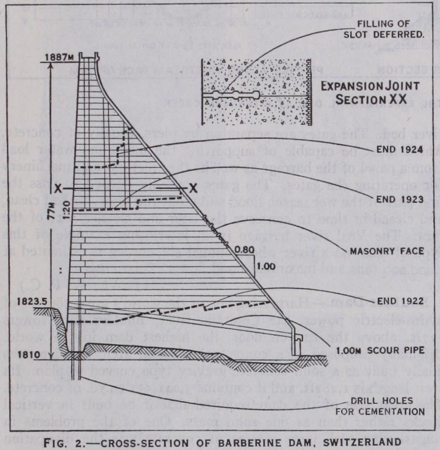
The Barberine dam in Switzerland, completed 1925, and shown in cross section in fig. 2 illustrates the application of the triangular form, together with excellent arrangements for sealing the base by cement grouting in drill holes, and for providing for ex pansion and shrinkage in the upper part. The dam is of concrete with mixtures varying from 250 to 30o kg. of cement per cu.m., is without drainage arrangements and is designed for water uplift on the base varying from full-head at the inside to zero at the outside. The slope of the waterface is 1:2o and of the outer face o.80:1. The section indicates an infrequent masonry facing of gneiss applied on the outer slope, which has a southern exposure and is subject to severe temperature variations.
The highest dam of this type yet projected is the Shasta dam of the Central Valley reclamation project which is to have a maximum height of 56of t., a downstream slope of 0.80 :1 and will contain over 5,500,00o cu.yd. of concrete. The reservoir with a capacity of 4,500,00o ac.ft. will be one of the largest.
The first arch dams were constructed generally with a constant radius throughout, with a resulting variation in the central angle. Increased economy in concrete can be obtained by Jorgensen's constant angle system of construction whereby the radius of the arch increases from the bottom of the dam to the top in accord ance with the varying width of the gorge. The largest dam of this type, constructed in 1934, is the Sautet dam on the Drac river, a tributary of the Rhone river, with a maximum height of 414ft., thickness varying irregularly from 8ft. at the top to 56ft. at the bottom and radius of the water face varying from 23oft. at the top to about 85ft. at the bottom.
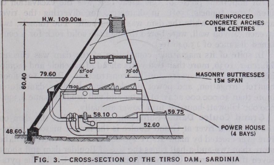
In multiple arch dams the buttress spacing may be from 15 to 6o ft. depending on the general height of the dam. The highest multiple arch dam constructed in Europe to 194o is the Tirso dam in Sardinia. The buttresses, spaced at 5o ft. centres, are of masonry with courses sloped at the outer face to suit the direction of maximum pressure and are designed to be independently stable and safe under the maximum loadings transmitted to them by the arches. The arches are of concrete, nearly semi-circular, lightly reinforced for temperature and shortening stresses, and have a thickness varying from 20 in. at top to 54 ft. at bottom.
The dam provides storage for the triple purposes of power production, irrigation, and river regulation, the power house being worked into the space between the buttresses.
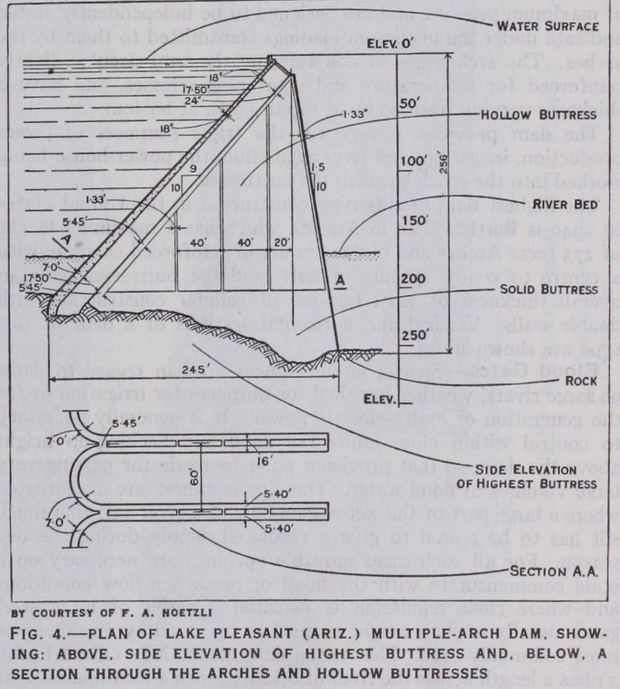
The highest dam of this type constructed in the United States to 194o is Bartlett dam in Arizona which has a maximum height of 273 feet. Arches and buttresses are of reinforced concrete with a centre to centre spacing of 6oft. and the buttresses have an overall thickness of 22ft. but are of cellular construction with double walls. Vertical and horizontal sections of a dam of this type are shown in fig. 4.
The Dnieprostroy dam on the Dnieper river, built for the Soviet Government, is the largest low head dam in the world constructed for hydro-electric power purposes. Gate and spillway arrangements are provided on a scale sufficient to pass a flood of 1,25o,000 cusecs. Power can be developed up to 56o,000 kw.
For the extreme case of a river transporting great quantities of silt where the barrage must not be allowed to become a trap for the settlement and accumulation of large quantities of material brought down during high floods, a continuous series of gates is used extending from bank to bank and having their sills at the river bed. The gates are separated by piers, usually of concrete, which must be capable of supporting the maximum water load from a panel of the barrage as well as the erections and machinery for operating the gates. The gates are fully opened to pass the first part of the wet season flood and scour the reservoir bed clean, and closed in time to conserve the later and cleaner part of the flow. The Vaal river barrage is an interesting example of this type of dam, on a river whose annual silt burden is estimated at 1,200,000 tons and maximum flood flow 187,000 cusecs.
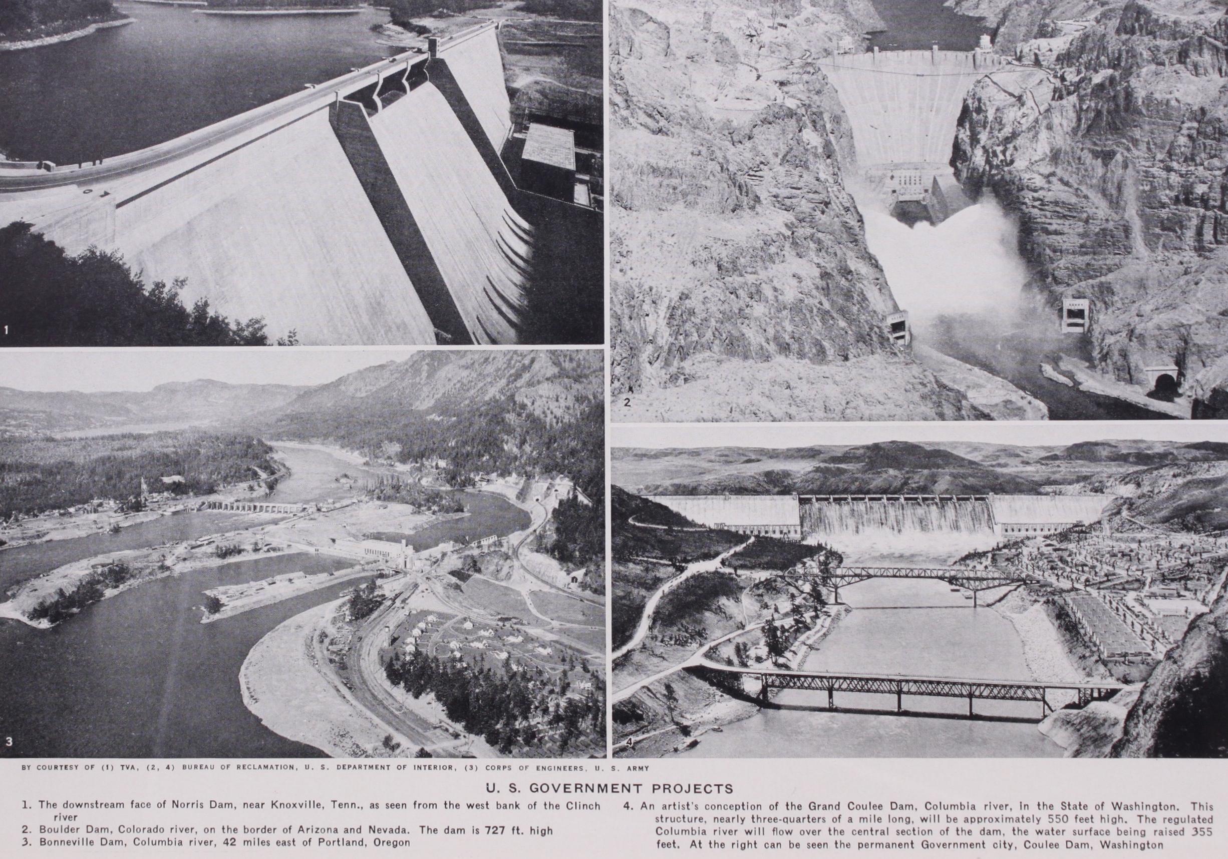
(J. WI.; W. P. C.) Boulder Dam.—Harnessing one of the world's great sources of hydro-electric power, the Colorado river, Boulder dam towers 727ft. above the canyon floor, the highest dam in the world. Originally proposed as a concrete horizontal arch, the dam was finally built as a solid concrete gravity type curved in plan. Its crest length is 1,282ft. and it contains 3,241,553 cu.yd. of concrete. The great size of the dam required that it be built in vertical blocks rather than as one solid mass. One of the problems in constructing such large masses of concrete was the dissipation of the heat generated by the hydration of the cement in order to prevent any large amount of expansion and contraction after the concrete had taken its initial set. For this purpose more than 57omi. of in. tubing were buried in the concrete and refrigerated water pumped through them.
The concrete for the dam was supplied by eight mixers, each with a capacity of four cubic yards. These were located in two plants, one in the canyon for the lower half of the structure, and the other on the canyon rim for the remainder. Construction was facilitated by the erection of a huge cableway suspended over the site for transfer of concrete and other construction materials to all parts of the dam.
An important phase of this great task was the excavation of four large tunnels, soft. in diameter, for diverting the river around the site while the dam was being built. The tunnels, two in each canyon wall, were bored through the solid rock for a com bined distance of 15,946 feet.
In spite of its magnitude, completion of the dam was effected March 1, 1936, more than two years ahead of schedule and requir ing less than five years for its construction. Built for flood control, irrigation, and power development, Boulder dam stores more than 3o,000,000 ac.ft. of water and will produce some 4,33o, 000,000 kilowatt-hours of firm power annually.
Grand Coulee dam is situated at a point where a glacier once dammed up the river forcing it to find a new course. Later the glacier receded and the river returned to its original bed 600ft. below, leaving a dry canyon somi. long and 2 to 5 mi. wide, now known as Grand Coulee. Part of the hydro-electric power gener ated at this dam will be used to pump water from the reservoir be hind the dam into another reservoir which will be created in the upper end of the Grand Coulee by constructing two earth and rock fill dams across it. This will involve lifting the water a maximum of about 37o feet. From this reservoir the water will flow through approximately 25omi. of main canal to irrigate the fertile basin of the Columbia river in the area known as the Big Bend. The Grand Coulee dam is 5 5of t. high, with a base width of 48oft. at its maximum section. Its total length is 4,5ooft. with 1,65oft. of this used as a spillway capable of passing a flood of i,000,000 cu.ft. per second. Such a flood would create a fall of water 5 times the average flow of Niagara Falls and 3 times as high.

The tremendous size of the dam presented the same construction problems as did Boulder, with the dam built in individual verti cal blocks, usually about 50f t. square. Cooling water was circu lated through 2,2oomi. of 1 in. tubing. A unique construction fea ture was the use of a system of long conveyor belts to transport materials from the excavation and to deliver concrete aggregates.
Assisting materially in flood control and river regulation, Grand Coulee dam has a storage capacity of 9,610,000 acre feet. Ulti mately nine generators will be housed in each of the two power plants at the dam. Their total capacity will be 2,550,000 horse power. The energy from six of the generators in the plant on the west side of the river is to be used for pumping. The remainder is to be sold to the market that is expected to develop when the irrigated land comes into use. The generators are expected to produce over 8,1 oo,000,000 kilowatt-hours of firm power annually.
On Sept. 22, 1938, with over 95% of the fill completed, there occurred a considerable movement of the material in the upstream face of the dam near the east abutment, involving approximately 5,000,00o cu.yd. of fill. The damaged portion was entirely re moved and rebuilt causing a delay of over a year in the final corn pletion time of the structure.
Fort Peck will store 19,500,000 ac.ft. of water, exceeded only by Lake Mead, the storage reservoir created by Boulder darn.