
DESCRIPTIVE GEOMETRY is concerned with the meth ods of making accurate drawings to represent completely any ob ject and to solve, with instrumental precision, problems relating to the position and shape of the object. It forms the theoretical basis of all architectural and mechanical drafting, and its practical applications are found in the drawing of machinery, buildings, bridges, vessels, in the representation of shades and shadows, in the construction of maps, and in the graphical solution of spheri cal triangles. It is the means by which the designer conveys his ideas to the builder or mechanic, and has been called the universal language of the engineer.
By the methods of descriptive geometry the solution of any problem concerning three-dimensional objects involves the follow ing steps: (I) representation of the lines, surfaces, or solids in space by corresponding plane figures; (2) solution of the problem by means of the plane figures; (3) interpretation of this solution as a relation between the objects in space. In order to carry out these steps it is necessary to have a definite scheme by which it is possible to pass without ambiguity from the object in space to its representation by drawings in a plane, and also without ambiguity from the drawings to the object in space again. The scheme now universally used for this purpose was devised about the end of the i8th century by G. Monge (1746-1818).
The orthographic projection of a point a upon a plane is the point where a line from a perpendicular to the plane meets the plane. The ortho graphic projection of a point a in a room upon the floor is the point on the floor directly under the given point a. The projec tion upon a plane of any object in space is the figure on the plane made by projecting each point of the given object. For example (fig. I) the plane of the square abcd is parallel to the plane H and the projection of abcd upon H is an equal square a'b' c'd' If (fig. 2) the edge ab is parallel to H but the plane abcd is not parallel to H, the projection of the square abcd on H is the rectangle a'b' c'd' in which a'b' =ab but b'c' is less than bc. If (fig. 3) the edge ab is parallel to H and the plane of abcd is perpendicu lar to H, the projection of the square abcd upon H is the straight line a'b' =ab. In fig. 4 the plane abcd is per pendicular to H and the diagonal ac is parallel to H. In this case the projection of the square is the line a'c' =ac.
The line aa' which projects a point a upon a plane is called a projecting ray, or projector. In orthographic projection the pro jecting rays are perpendicular to the plane of projection; conse quently all projecting rays are parallel. An oblique projection is obtained when all projecting rays are parallel but are not perpendicular to the plane of projection. Oblique projection is used in the construc tion of shades and shadows. When the projecting rays are parallel the size of the projection does not depend upon the dis tance of the object from the plane of projection.
A scenographic projection, or perspective (see PERSPECTIVE) is obtained when all of the projecting rays converge to a single point, the point of sight (fig. 5). This method produces a picture or representation of an object, or group of objects, as it appears to the eye. The size of the scenographic projection of an object depends upon the distances from it to the point of sight and to the plane of projection.
Unless otherwise specified, projection usually means orthographic projection.
Monge's method of representation of an object consists in making orthographic projections of the object on two (or more) planes and establishing a definite relation between the different projections.
The two principal planes are the vertical (denoted by V) and the horizontal (de noted by H). The line of intersection of these planes is called the ground line (de noted by GL). Except for special cases H and V are sufficient for the solution of the problems of descriptive geometry. When a third plane, the profile plane (denoted by P), is desirable it is taken perpendicular to GL and is therefore perpendicular to both H and V.
The projection of an object on the vertical plane is called the 17-projection or elevation; the projection on the horizontal plane is the H-projection or p/an. In commercial terminology the ele vation is called also the front view, or rear view, or sectional eleva tion, as the case may be. The plan is called also the top view, bot tom view, or sectional plan. Similarly, we have the profile or end view.
The two principal planes of projection are supposed to be un limited in extent and divide space into four compartments called quadrants or angles. In order to distinguish among these quad rants imagine an observer look ing at the planes as they appear in fig. 6. He is above H and in front of V. This is the first quad rant. The second is above H and behind V. The third is below H and behind V. The fourth is be low H and in front of V. An end view is shown in fig. 7.
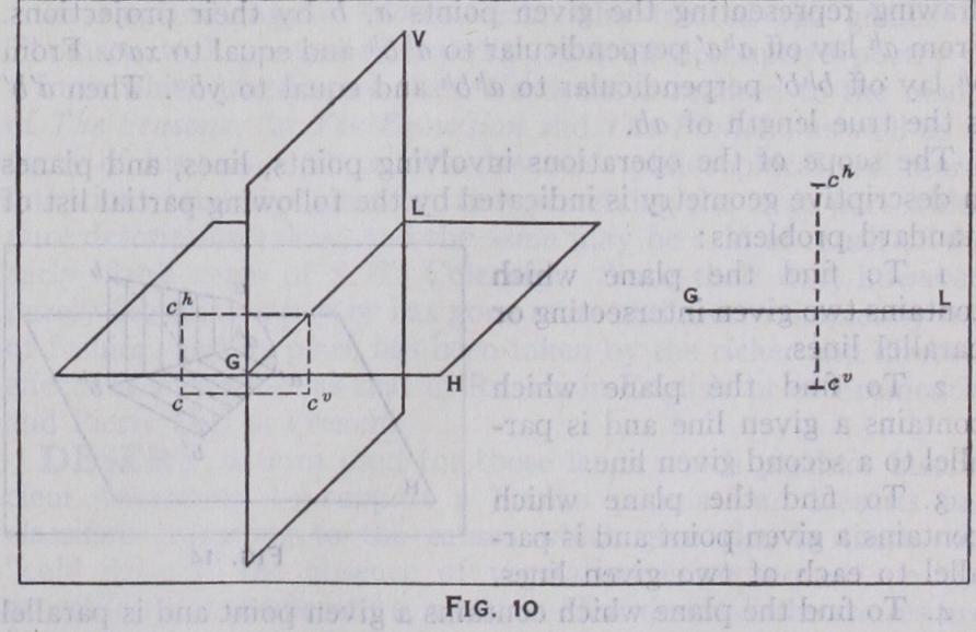
The method of Monge for representing the position of a point in space by a plane drawing consists in turning the V-plane about GL as an axis until it coincides with the H-plane. The direction of rotation (fig. 7) is such that the upper part of V is made to coincide with the part of H which is behind GL.
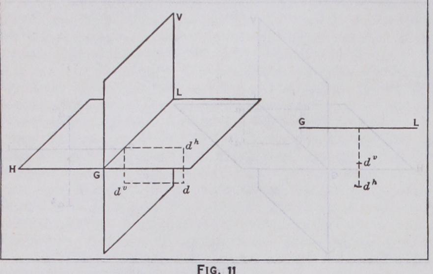
It is one of the fundamental relations of orthographic projection that, in space, the two projections of any point together with the point itself must always be in a plane which is perpendicular to GL. After revolving V, the two projections of any point will lie in a straight line which is perpendicular to GL. The relation be tween a point in space and its plane repre sentation is shown for each quadrant by figs. 8–ii.
In architectural drawing the objects are usually supposed to be located in the first quadrant, so that the elevation appears above the plan. In engineering drawings the objects are usually in the third quad rant. In perspective drawing the objects are usually in the second quadrant. The fourth quadrant is little used in practice.
1. If a line of definite length is parallel to V alone, its V-projec tion is parallel and equal to the line, and its H-projection is paral lel to GL.
3. If a line is parallel to H and V, both of its projections will be parallel to GL.
The projection of a line ab in space will be the lines joining the projections of a and b, that is (fig. 12), the V-projection of ab is avbv and the H-projection is alb".
In general, any two lines assumed as projections in the plane drawing will determine a line in space. There are, however, excep tions when one or both of the projections are perpendicular to the ground line.

A line of indefinite length, which is parallel to neither principal plane, will pierce H in a point called its horizontal trace and will pierce V in its vertical trace. These special points are sometimes used to represent the line in the drawing.

I. If a plane is parallel to V, it has no V-trace and its H-trace is parallel to GL.
2. If a plane is perpendicular to V, but oblique .to H, its H-trace is perpendicular to GL.
3. If a plane is parallel to neither principal plane, its traces will either (a) both be parallel to GL, or (b) intersect GL in the same point.
A profile plane is perpendicular to both H and V. If a plane contains GL, it is represented by its trace on a profile plane.
In the plane drawing (fig. 13) any two lines which meet GL at the same point may be taken as the traces of a plane, and they completely determine the position of the plane in space.
The solution of a problem by the methods of descriptive geometry may be illustrated by the following simple ex ample: Problem.—To find the true length of a line joining two given points in space.
The scope of the operations involving points, lines, and planes in descriptive geometry is indicated by the following partial list of standard problems : I. To find the plane which contains two given intersecting or parallel lines.
2. To find the plane which contains a given line and is par allel to a second given line.
3. To find the plane which contains a given point and is par allel to each of two given lines.
4. To find the plane which contains a given point and is parallel to a given plane.
5. To find the plane which contains a given point and is per pendicular to a given line.
7. To find the line of intersection of two planes.
8. To find the point in which a straight line intersects a plane. q. To find the shortest distance from a point to a plane.
1 o. To find the perpendicular distance between two parallel planes.
To find the projections of a line making given angles with H and V.
12. To find the angles which an oblique plane makes with H and V.
13. To find the angle between two intersecting lines.
14. To find the angle between two planes.
15. To find the angle between a line and a plane.
16. To find the shortest dis tance from a point to a line.
17. To find the shortest dis tance between two lines not in the same plane.
18. At a given point in a plane, to draw a line which shall be perpendicular to the plane and of given length.
Fig. 18 represents the develop ment of the spout of a teapot. The problem involves the inter section of two conical surfaces. The development furnishes a pat tern for cutting the metal from which the spout is made.
Descriptive geometry is a regular study in the curriculum of engineering students, and books on the subject are to be found in the list of every prominent publisher of educational texts for technical schools. (W. R. L.)