
THE CONSTRUCTION OF DOCKS Up to the last quarter of the t gth century masonry construc tion was adopted for the large majority of dock works such as quay walls and locks, and hydraulic limes to a limited extent took the place now occupied by Portland cement. The use of Port land cement concrete for all kinds of port construction is now almost universal, and its cheapness in comparison with the cost of dressed stone in the large majority of situations has restricted the employment of the latter to such purposes as copings and sills, altar courses in dry docks, etc. As an example of this change in practice, the Rosyth dockyard (1909-18) may be mentioned. Practically all British naval docks built prior to r 905 are faced throughout, or at any rate on all important surfaces, with dressed stone, usually granite. In the case of Rosyth, however, the quay and dock walls are built of and faced with concrete, dressed granite being used only for copings, quoins, sills and similar work.
Reinforced concrete has been used in building jetties, wharves and other dock works since about 1895, and its employment is extending. In a considerable measure it has superseded timber in the building of openwork jetties and wharves, particularly in waters where marine borers such as the Teredo (q.v.) and Lim norie are present. Rapid setting aluminous cement (q.v.) came into use on the continent of Europe about 192o, and its employ ment in the United Kingdom was growing rapidly in 1928; but its suitability for use in sea water had not been fully tested by the lapse of time. Pozzuolana and trass cements (see CEMENTS) are largely employed on the continent of Europe, usually in com bination with Portland cement.

Excavations for Docks.—When a dock has to be made on land the excavation is performed by men filling wagons, which are hauled by locomotives to the place of deposit, or "skips" (large steel buckets) which are lifted by cranes and tipped into wagons at a higher level. When, however, the conditions make it prac ticable and economical steam or electric navvies or excavators are employed in preference to hand labour. A form of land dredger is also sometimes used for large excavations in light soil, and aerial ropeways, dragline excavators and various forms of electric conveyors find their uses in excavation. Frequently a large part of the interior excavation (called the "dumping") of a wet dock or basin is left to be dredged away by floating dredgers after the walls of the thick have been completed and water has been ad mitted to the area.

When the standing water level in the soil is reached, the water has to be removed from the excavation by pumps drawing from sumps sunk down below the foundations in suitable positions so that the lowest portions of the dock walls and other structures may be built out of water. A method of draining the working area which has been adopted in Holland and Belgium in the case of several docks built since 19io in sandy or alluvial soil, is to sink filter wells at intervals round the dock area outside the lines of the permanent works. The suction pipes in the wells, which are sunk to a depth below the deepest foundation, are connected up to one or more pumps which, working continuously, lower the standing water level in the ground to be excavated to the required amount. Interlocked steel sheet-piling is often employed to cut off water which would otherwise percolate into an area to be excavated.
In many cases of dock building a cofferdam has to be con structed cutting off the entrance works from the river or harbour water. This cofferdam is removed when the works built within it have been completed. When a dock is to be constructed, partially or wholly, on reclaimed land, a reclamation bank for enclosing the site and excluding the tide may be necessary, as in the con struction of the King's Dock, Swansea. In some cases, however, the wall forming the outer boundary of the dock has been built by sinking concrete monoliths from temporary staging erected on the foreshore or sea bed. This plan was adopted to a partial extent in building the enclosing wall of the Rosyth Dockyard basin ( 19o9-1 5).

The nature of the strata to be excavated and on which the walls are to be founded is ascertained by trial borings and, when prac ticable, by sinking trial pits. The nature of the foundation has an important bearing on the design of the wall and its method of construction. Ordinarily, hard clay (such as boulder clay), com pact gravel and sand, as well as most rocks form excellent founda tions. It is, in these cases, usually unnecessary to carry the base of the wall more than a few feet below the dock bottom. In less satisfactory ground, however, such as slippery clay and alluvial material, and sand charged with water, the foundations may have to be carried down to a considerable depth and the base width increased. Timber bearing piles are sometimes driven to form a foundation for a wall. In other cases a trench has been dredged in the soft material along the line of wall and filled with ballast or stone or even coarse sand to provide a sound foundation.
The walls round a dock serve as retaining walls; and, though they have the support of the water in front of them when the docks are in use, they have, when built and before the water is admitted, to sustain the full pressure of the filling at the back, as well as any surcharge due to erections on the quay. The com pletion of the filling behind the wall is on this account sometimes deferred until af ter the dock is filled with water.
The thickness of solid dock walls is increased downwards to support the pressure which increases with the depth. This pres sure depends on the nature and angle of repose or natural slope of the ground and filling material behind the wall. But the pres sure is often increased by the accumulation of water at the back, which with fine silty material, is liable to exert a sort of fluid pressure against the wall proportionate to the density of the mix ture of silt and water. The increase of thickness towards the base used formerly to be effected by a batter on the face, as well as by stepping the back. The vertical form now given to the sides of ships necessitates, however, a corresponding vertical, or nearly vertical, face for the wall.
The height of a dock wall above the dock bottom depends upon the minimum depth of water always available for vessels, and the rise of the tide. In tideless sea-ports and inland ports removed from tidal influence, the height is represented by the minimum depth of water plus a margin of from 6 to I oft. from the water level to the quay surface. At tidal ports, however, an addition has to be made equal to the difference in height between the highest and lowest water levels in the dock or in the open basin as the case may be. At some ports, e.g., Montreal, provision against river floods, etc., necessitates especially high coping levels.

Under normal conditions, a solid or gravity dock wall should be given a width at a height halfway between dock-bottom and quay level, not less than of its height above dock bottom, and a width of about half this height at dock bottom. Conditions, however, are so largely governed by the nature of the strata that every case has to be dealt with on its merits.
Dock walls are constructed of masonry, brickwork or concrete, or of concrete with a facing of masonry or brick. The bulk of recent dock wall building has been in concrete and, when suitable materials are available at or near the site of the works, concrete construction is usually cheaper than any other form. Where no extraordinary difficulty is to be apprehended the foundations for dock walls, below the level at which open excavation is practicable and economical, are excavated in a trench. The trench is lined with timbering for the support of the sides during excavation and, in bad ground and very deep trenches, timber sheet-piling or interlocked steel sheet piles are driven to form the sides. Exam ples of dock walls built in trenches are shown in figs. 6 and 8.
The walls of open basins are often constructed in the dry pre cisely like dock walls as in the case of some of the basins at Glasgow. They differ only from dock walls in being exposed to variations in the pressure at the back resulting from the lowering of the water-level in front. This feature is, indeed, shared to some extent by the walls round closed docks where the difference in the high water levels of springs and neaps is considerable. The walls, however, round basins in tideless seas, such as Marseilles, occa sionally those inside harbours and docks, and especially quay walls along rivers, have to be constructed under water. If mass concrete walls are to be built in the dry some form of cofferdam is necessary when the site is covered by water and steel sheet piling is now commonly employed for the purpose of enclosing the area to be excavated.
Recently quay walls have been built by Italian and French en gineers with concrete blocks weighing up to about 40o tons set one above the other on a foundation of rubble or on a prepared rock bed (fig. Io). Both cellular and "cyclopean" (solid) blocks have been employed for this purpose. (See also BREAKWATER.) Sloping blocks (see BREAKWATER) were used many years ago in the construction of a quay wall at Marmagoa, on the west coast of India, erected on a foundation layer of rubble, to provide against unequal settlement on the soft bottom. The system has often been employed since. Recent examples are the quay walls of Valparaiso and Kilindini (Mombassa) harbours.
Monoliths were employed at Tilbury in building the walls of the main dock extension (fig. 13) and at Calcutta for the new docks (1928) where the soil is alluvial of a very soft character. At Rosyth some of the monoliths sunk for forming the outer walls of the dock were carried down to a depth of I 2 'ft. below the cop ing before a sound foundation was reached (see Proc. Inst. C.E. 1927). When monoliths have been sunk to the required level the well spaces are sealed with concrete. In some cases the wells are entirely filled with concrete, in others sand filling is used above the concrete seal at the bottom. In some instances, as at Tilbury and Karachi, the front wells are only partially filled to reduce the intensity of pressure on the foundations at the toe of the wall.
Quay Walls, Wharves and Piers on Piled Foundations.— In many cases where soft strata extend to considerable depths, river and basin quays have been constructed by building a com paratively light wall upon a series of bearing and raking piles driven into, and if possible through, the soft alluvium. Thus the older quay walls at Rouen were built upon bearing piles carried down through the alluvial bed of the river to the chalk. The lower portion of the wall was built of concrete and brickwork within water-tight timber caissons resting on the piles at a depth of 8 to 'oft. below low water.
The pier and wharf walls in the port of New York and other North American harbours are frequently built on bearing and raking piles. These are some cases where the soft silt into which piles have been driven is so deep that no firm stratum could be reached and the supporting power of the piles has been increased by tipping large quantities of stone rubble and gravel around them before and after they were driven.
Many of the basin and quay walls at Bremen, Hamburg and other German ports are also built on bearing and raking piles, the wall being begun a few feet below low water. At Rotterdam timber piling in combination with fascine work was used for many of the older quay walls.
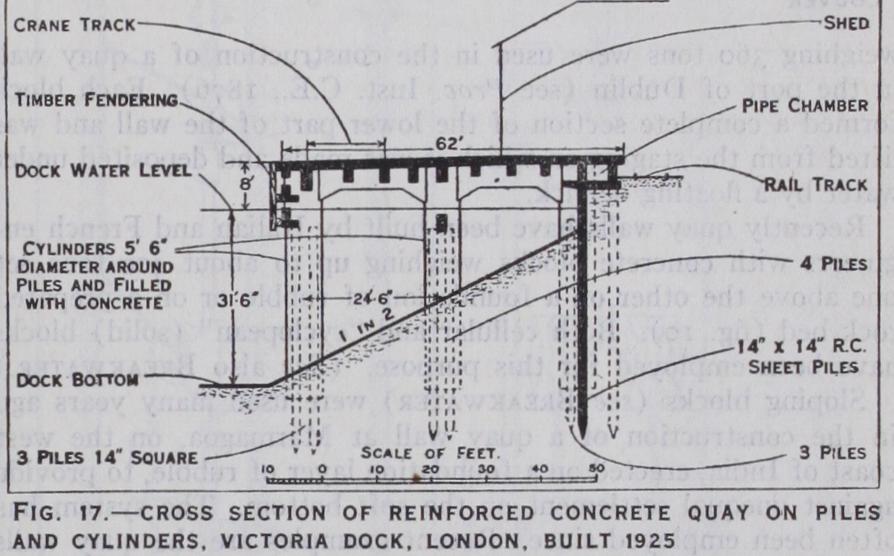
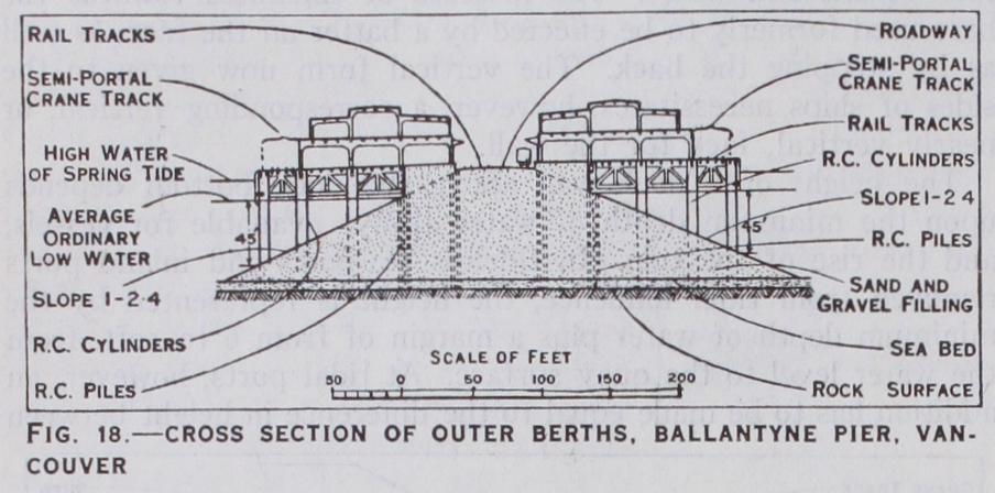
Reinforced concrete piles have been used in substitution of tim ber piles to an increasing extent since about 190o for foundation piling under solid superstructure walls, but in waters where marine borers are not present as, for instance, at Amsterdam and Ham burg, timber is still employed and has a long life in positions where it is always submerged. Reinforced concrete is also widely used for building the superstructures of wharves (figs. 16-17) as well as for the piles on which they are built. At Madras piles 25in. square and over 75ft. in length were employed in building a deep water wharf completed in 1928. Substantial piers and wharves have been built by driving clusters of reinforced concrete piles inside cylinders of that material sunk below the dredged level of the berth. The spaces between the piles and the surrounding cylinders are filled in solid with concrete. In some cases cylinder foundations are sunk without piles. An example of this construc tion applied to the typical North American wide pier or jetty is seen in the Ballantyne pier at Vancouver (fig. 18), completed in 1923. It is 1,2ooft. long, 341ft. wide, with a depth of water in the berths of 45ft. at low water. The hearting of the pier is formed of sand and gravel filling; the outer rows of columns are 7f t. diameter reinforced concrete cylinders and the inner rows clusters of piles. Economy in construction is sometimes obtained by forming sloping sides to part of a dock or river frontage in place of vertical quay walls. Jetties or open wharves of timber or rein forced concrete can be carried out across the slope, as at many coal-shipping ports; and the length of the slope projection into the dock is sometimes reduced by substituting sheet piling for a -portion of the slope at the toe or at the upper part.
A type of open-work quay wall much used in Dutch and Scandi navian ports is shown in fig. 16. The example shown is built on timber piles, but in some cases reinforced concrete piles are used.
The Tilbury river jetty (fig. 5), completed in 1921, is an ex ample of a cargo wharf in tidal waters where the spring tide range is 211t. The design of this jetty is hardly typical as it is intended to deal with special conditions of part-cargo traffic.
In tropical ports materials for concrete construction, as well as skilled labour, are occasionally difficult to obtain and the use of timber for wharf construction may be unsuitable on account of the ravages of marine borers. These conditions exist, for instance, in some ports of .East and West Africa and in them open work wharves and jetties have been built of mild steel completely fabricated in European or American works and sent overseas ready for erection. Screw piles are frequently used where the foundations are suitable, and timber is employed for the decking.
Reinforced concrete in wharves and jetties is liable to damage by vessels, and such damage is often more difficult and costly to repair than timber construction in similar positions. It is, there fore, important to provide substantial timber fendering on the face of such works.
A dock wall founded on a soft bottom is liable to settle down at its toe, where the intensity of pressure is greatest, and to fall forward. It is found, however, that the most common form of failure is the sliding forward of a dock wall, with little or no subsidence, on a slippery or silty stratum under the horizontal pressure imposed by the backing. The second of these alterna tives was probably the cause of the failure of the Empress basin wall at Southampton in 1888-89. The last form of failure is illustrated by the sliding of the Kidderpur (Calcutta) dock walls in 1890, and of a part of the south West-India dock walls in 1870.
The risk of failure can be minimized by: (a) the use for back ing of the best hard material unaffected by water; (b) the pro vision of temporary drainage pipes through the wall during con struction to prevent the accumulation of water at the back of the wall; (c) deferring the completion of the backing until after the admission of water to the dock; (d) making the base of the wall slope downwards towards the back, thereby forcing the wall in sliding forward to mount the slope or to push forward a larger mass of earth; and, most important of all, (e) carrying down the foundations sufficiently below dock-bottom to provide an effi cient buttress of earth in front of the wall, thus increasing the resistance to shearing of the strata at the base of the wall, and the lateral resistance in front of the toe.
In order to spread the weight of a wall and decrease the in tensity of pressure at the toe, and thus increase its stability, many modern quay walls have been built with a projecting toe, some times reinforced by steel bars (fig. 8) .
Entrances have the advantage of occupying less room than locks and they are much less costly; but they are under the important disadvantage of being accessible for a limited period only on each tide. They have been seldom included except as auxiliary passages, in the construction of large new docks.
The inner and outer sills of dock locks are frequently con structed at the same level; but at some ports, particularly where the tidal range is large, as in the Bristol Channel, the outer sill is laid at a lower level than the inner one. This effects an econ omy in the cost of construction especially in large modern locks designed to admit a vessel at or near low water, in which case it is necessary to place the sill at a considerable depth. On the other hand there is an advantage in all the sills being at the same level, particularly where there are three pairs of gates, as the gates are then interchangeable. Moreover, in docks where the en closed water is not maintained at a high level by impounding pumps or by the inflow of land water, the depth in the dock, and consequently over the inner sill, is reduced at neap tides by the loss of lockage water. In some cases, also, the construction of the inner sill at a low level is desirable in view of the possible future deepening of the dock itself.
The inner sill of the King George V. lock (London), although the dock water is impounded by pumping at a level of 22ft. above T.H.W., was constructed at the same level as the outer sill and about I oft. deeper than the general surface of the dock bottom. The impounding at the King George V. dock is consequent on its being connected by a passage with the Albert dock, where the necessary increase in depth had been effected by this means. The Gladstone (Liverpool) lock sills are also all at the same level but, in this case, the level of the dock bottom is approximately the same as that of the sills and no provision is made for impounding.
On the other hand, the inner sill at Rosyth is laid at dock bottom level or 131 ft. above the outer sill. The sills of intermediate gates are always placed at the same level as the outer sills.
The foundations for the sills, side walls and invert or floor of a lock are generally constructed un der shelter of a cofferdam across the entrance channel, and the ex cavations are kept dry by pump ing. Under sills and the adjacent walls the foundations are usu ally carried down to a lower level than the rest and, if possible, to an impervious stratum, to pre vent infiltration of water under them owing to the water pressure on the upper sides of the gates. Sometimes permanent sheet pil ing is driven across the lock site under the sills, and occasionally under the side walls also, to cut off the flow of water.
The sills, projecting about 2 or 21 ft. above the gate floor, and the hollow quoins are almost al ways constructed of granite, carefully dressed to a smooth and true surface. The hollow quoin is the vertical concave recess formed in the wall, in which the heelpost of the gate turns, and is exposed to considerable wear. Other part of the lock structure are ordinarily built of concrete except the coping courses which also are frequently of granite.
The side walls of a lock chamber are very similar in construc tion to dock walls; but they are strengthened against the loss of water pressure in front of them, when the water is lowered in the chamber, by the floor or "invert" of the lock, usually built of concrete and sometimes constructed in the form of an inverted arch. This invert prevents any forward movement of a sidewall, the toe of which abuts against it. In some cases too it acts as an inverted arch and assists to resist any upward hydrostatic pressure under the floor when the lock water is run down. The side walls alongside the gates also abut against a thick level gate floor and apron and, moreover, are widened to provide space for the cul verts, sluice pits and gate machinery.
A feature in the design of all modern locks and entrances, in cluding those of dry docks, is the rectangular form of the entrance, approximating to the shape of the midship section of modern steamships. Most old entrances were constructed with inverted arch floors, the depth being greater in the centre than at the sides.
In situations where a lock has to be built in waterlogged alluvial strata of a soft nature it is sometimes necessary to sink concrete well monoliths in constructing the foundations : this has been done in building the locks at the King George dock, Calcutta and 'Tilbury (1928). Large caissons were employed for constructing, under compressed air, the foundations of the gate chambers, lock heads and portions of the side walls and floor of the Florida lock at Havre; V. The Engineer, 1908, et seq. A large lock at New Orleans, built in fine quicksand, is supported on 24,00o piles (see