Installing Electric Bells
circuit, fig, bell, push, shown and type
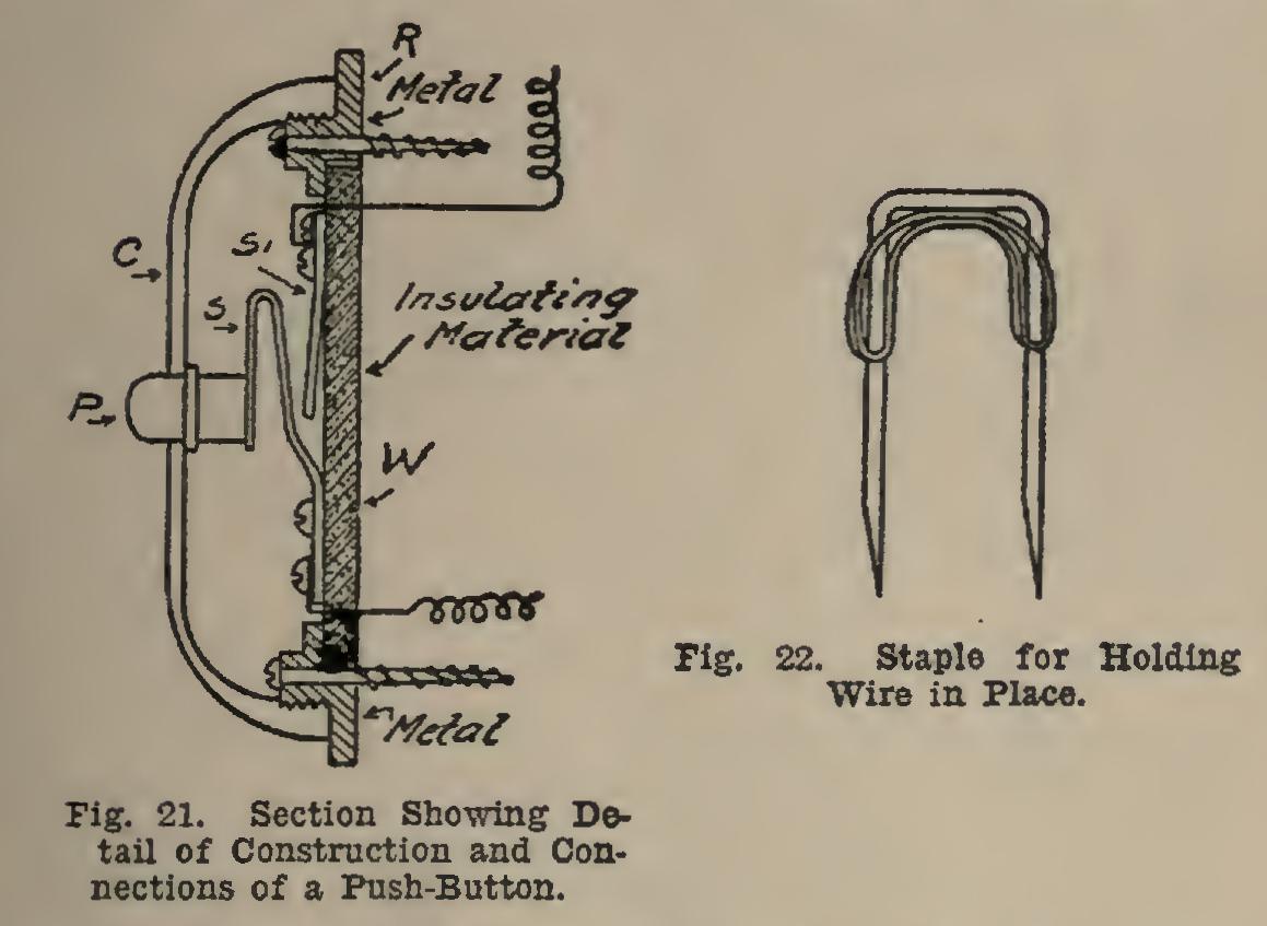
The wire used should be well insulated, and held in place by staples or cleats, making sure that there are no short circuits due to staples cutting the insulation. A good form of staple to use is shown in Fig. 22. It is found to be quite a great advantage to have the insulation of the wires in different colors, so that they may be easily indentified without testing, thus saving time when installing. The sizes of wire commonly used are Nos. 18, 20, and 22, B. & S. (Brown & Sharpe) gauge. Wires smaller than these are too weak from a mechanical stand point.

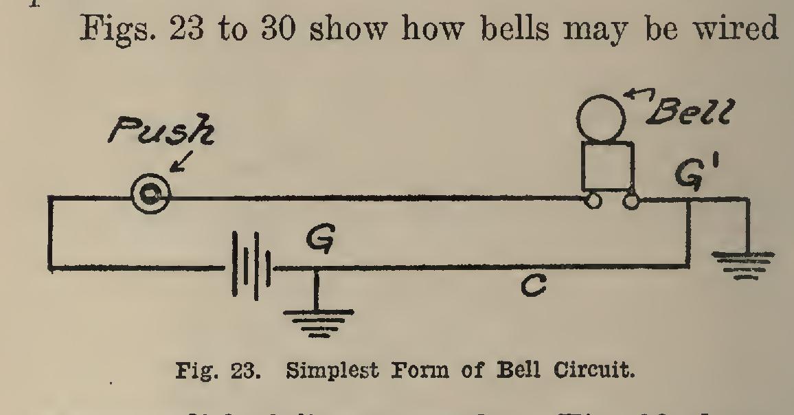
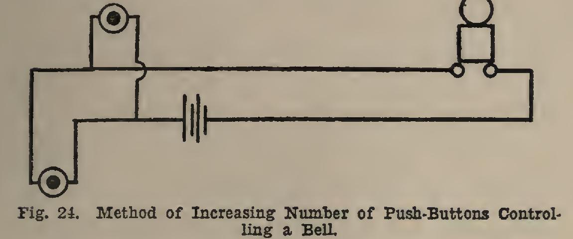
to accomplish different results. Fig. 23 shows the simplest circuit we can have. There can be a saving in wire by using what is termed a ground, the current being returned by connect ing to ground at G and thus dispensing with the conductor C. A ground connection may be made by connecting to gas or water pipe. The number of pushes controlling this bell can be increased as shown in Fig. 24.
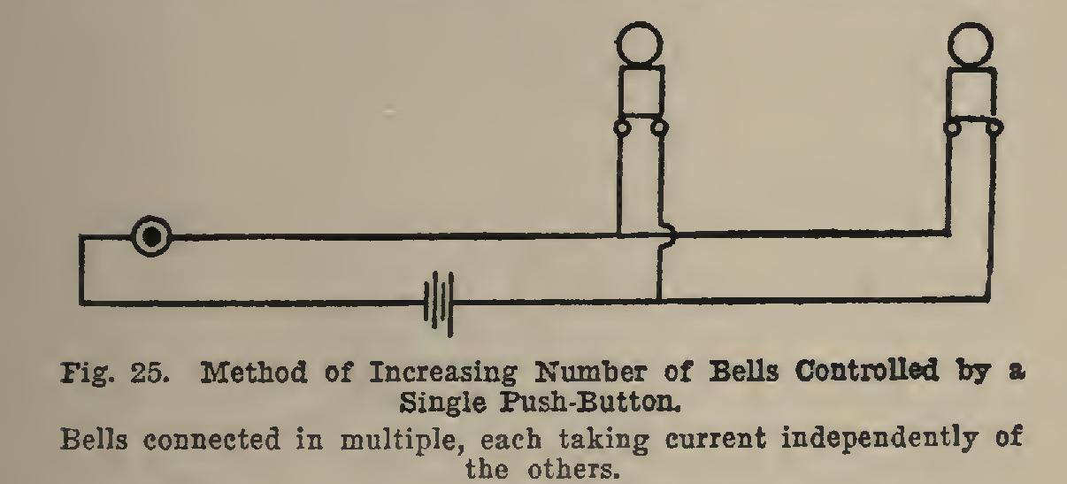
The number of bells controlled by a push button can be increased as shown in Figs. 25 and 26. The bells are connected in multiple in Fig. 25, and each takes current independently of the others. In Fig. 26, they are connected in series; only one bell in this case is of the vibrating type, it serving to make and break the circuit through the others.

Annunciators. Quite often it is desirable to have a bell ring from a number of different places, such as different rooms of a house, and a means must be provided for indicating the push from which the bell was rung. A device called an annunciator fulfils this requirement. Fig. 27 shows the circuit of a simple annun ciator, there being only four drops shown.
When any push is operated, there is sent through a coil in the annunciator a current cor responding to that push which causes the indi cator to drop, thus giving an indication of where the call was made from.
The indicators are restored to their original position by means of a lever at the bottom of the box, or may be restored electrically by press ing a push-button for this purpose.
Fig. 28 shows an annunciator suitable for residence work.
Burglar Alarms. The electric bell may be used as a burglar alarm, by having the circuit so arranged that a bell will ring when anything is disturbed—as, for example, by opening a door, by raising a window, by breaking a glass, etc.
The simplest circuit is practically the same as those just described, except that contacts are placed on doors, windows, etc., instead of using the push (see Fig. 29), and are so arranged that they will complete the circuit when the doors are opened or the windows raised. This is what is termed an open-circuit alarm, as the circuit is normally open.
Another type, known as the closed-circuit, in which the circuit is normally closed, is used in the following manner: A closed-circuit bat tery is connected in series with a relay, and, say, a strip of gold foil across a plate-glass window. This relay is normally energized; but if the glass is broken and the circuit thereby opened, the relay becomes de-energized, and its arma ture drops back, completing a local circuit con taining a vibrating bell (see Fig. 30).