Joint
plates, square, column, center, rivets and section
Both of these sections are greater than the section as designed in Fig. 71, which had only 27.00 square inches, but would be used if a Z-bar column is desired.
If a channel column is desired, (C 140) should be consulted. In the 8th column, and near the bottom of the page, 173.2 is found on the 30-foot line. This requires (see top of page to left of figure for width of plate) : (C 101) Two 9-inch 25-pound channels=14.70 square in. (C 250) Two 11-inch inch plates =17.88 square in.
32.58 square in.
By (C 141), it will be seen that two 10-inch 20-pound channels, and two 12 by plates, give 177.9 as the capacity; and computa tions will show an area of 30.86 square inches. A smaller section yet is that from two 12-inch 20.5-pound channels and two14 by%-inch plates. The area for this section is 29.61 square inches. A length of 32 feet is here used at the top line for values under that. The results of the areas are: Z-bar 32.65 sq. in.
Channel column 29.61 sq. in.
Angles and Plates column 27.00 sq. in.
from which it would appear that the Z-bar col umn is the most expensive section, and the an gles and plates the least. This, however, is not the case, for the small amount of riveting done in the Z-bar column—only two rows—more than offsets the saving in metal.
The channel section is next, with four rows of rivets; and the angles and plates are last, with four rows to connect the angles with the plates, and four rows to connect each side by means of lattices.
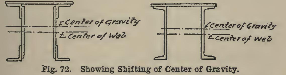
In some cases, bridge sections cannot have plates on both sides, as in the case of columns, since other members of the bridge must go in side of them. In such cases the plate is put on one side only (see Fig. 72). This changes the center of gravity of the section from the middle web to a position higher up; and the radius of gyration must then be computed as referred to this axis through the center of gravity. A great many sections of this character are given in Godfrey's Handbook (see pages 104 to 119), and to this the reader is referred in case it is desired to design such sections.

48. Rivets in Compression Members.
The spacing of rivets in compression members is not determined theoretically. The number of rivets must be such that sufficient should be put in be tween the center of the member and the end to transfer the stress from the angles to the webs or from the plates to the channels. In the tie plates, they are usually spaced 3 inches apart, or more, a sufficient number being put in to fill out the plate.
In Fig. 71, one angle is 3.75 square inches in area. On page 243 the allowable unit-stress is computed to be 12,639. Therefore each angle carries 3.75X 12,639=47,396 pounds. If the al lowable unit-stress in shear were given as 7,500 pounds, one rivet would stand (C 195) 4,510 pounds, and 47,3964-4,510=11 rivets would be required in the 15 feet on each side of the center. Here, as in most cases, the computed spacing would be too great, and the rivets are usually put in at a 4- or 5-inch spacing up to about three feet from the ends, where a 3-inch spacing is used for the remainder of the distance.
49. Loading of Compression Members.
The loading of compression members should be cen tral if the stress is brought on by means of a pin, as in a bridge the pin should be at the center of gravity of the member. If, as in case of col umns, the load comes on top or from beams which are connected to it, the load should be central and the connecting beams should be symmetrically joined in. Fig. 73 shows how con nections should be made in the case of pin ends and also in the case where 1, 2, 3, and 4 beams are connected to the column.
If columns do not have connections symmet rical and, as in case of one beam, at the center of the column, the stresses will be greatly in excess of those as computed, and the member may fail. Also, the columns should be so placed that the reactions of beams coming on opposite sides of it will be equal or as nearly so as possible. Fig.
74 shows some common framing practice which should be avoided.