Measurement of Masonry
load, beam, fig, pounds, wall, feet, square, weight, strength and length
To get the full benefit of piling, the piles should be bound together by a layer of concrete extending from the tops one or two feet down to the earth into which the piles are driven. Fig. 16 shows a section of such construction.

In Chicago a modification of piling is adopted which consists of digging a series of wells from 3.5 feet to 8 feet in diameter, down to suitable material. At the bottom, these wells are en larged considerably to secure better support, and the whole well is then filled with concrete. Such a well is shown in Fig. 17. The bed-rock is from 90 feet to 110 feet below the surface, and, of late, the foundations of the heaviest buildings have been carried to this depth.
Mechanics of Beams.
Before taking up the design of structures, it will be well to review briefly the mechanics of beams as given in ele mentary textbooks on the subject.
by 4 or 5 shows that the above beam should safely support from 23 to 29 pounds.
In
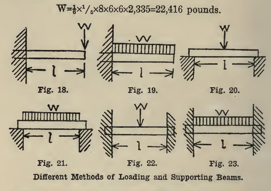
practice, of course, the beam would have other dimensions, and the formula shows that the result obtained above should be multiplied by the breadth and by the square of the depth, and divided by the length. Table V and the ac companying illustrations (Figs. 18 to 23), show the effect of different loadings and ways of sup porting the beam.
For example, a lintel of Troy, N. H., granite 5 feet long, 6 inches deep, and 8 inches wide, hav ing its ends fixed in the walls, carries a uniform load. From Table II, the strength is found to be 2,335 pounds per square inch. In Table V, the factor is which is always to be multiplied by the width and by the square of the depth, in inches, and divided by the length in feet. So the ultimate uniform load is For safety this is to be divided by 4, so that the safe load is • W=22,416+4=5,604 pounds.
If it be required to find the deflection of the same beam, or the bending moment of a beam of other than rectangular cross-section, it is nec essary to know the meaning of the symbols E and I. The first letter indicates coefficient of elasticity; and the latter, moment of inertia.
It is a well-known fact, verified by experi ments, that all materials will change in length when loaded; and that this change in length is exactly proportional to the loads, if the latter Design of the Footing. The footing courses of a building are so proportioned that the above named allowable unit-pressures on the soil are not exceeded. In other words, the total weight, divided by the safe load, will determine the total area of the footing. In most cases where the foundation is not on rock, there will be more or less settling; and the best that can be done is to make this uniform over both outside and inside walls. The weight on each wall should be es timated as nearly as possible, and the width of the footings made to correspond.
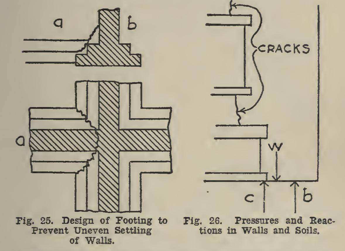
In Fig. 25 the cross-wall a has settled less than the outside wall b, and an irregular crack has been occasioned as shown. The remedy is to increase the width of the footing of b, or to decrease that of a.
The effect of the relative positions of the downward weight and of the upward reaction of the soil, is shown in Fig. 26. It is nearly im
possible to make these exactly opposed to each other; but it is manifestly better that the wall a have a slight tendency to lean toward the open ing than from it. This is the result when the upward reaction is at b rather than at C, when the weight of the wall is centered at W; and it is clear that the footing should be narrower or alto gether omitted under the doors and windows. It is impracticable to state this rule very def initely, since there is always considerable rig idity in the masonry, which makes it impossible to fix the exact point of application of the up ward reaction of the soil. However, in general, the ends of a wall should have rather better support than the middle parts; and the outside walls better than those in the interior.
Eccentric loading. In
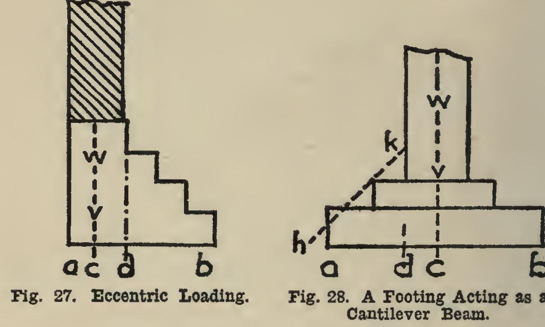
city lots the space is so valuable that the footings do not extend much outside the walls. The result is that the loads due to the weight of the building are applied as shown in Fig. 27, and the pressure at a is greater than at b. When be is twice ac, the pressure at a is twice the average pressure on ab, and that at b is zero. This question will be more thor oughly investigated below, under the heading "Retaining Walls." The addition of width, as db, actually increases the unit-pressure at a unless db is twice ad.
Strength of Footings. In
designing foot ings, it has been the custom to consider the part projecting beyond the pier as a cantilever beam (see Fig. 19). Thus, in Fig. 28, the length of the beam has been taken as ad. Experiments prove that the footings often do fail in this place, but through shear rather than bending. If the foot ing be considered as a cantilever beam (Fig. 28), with a load W upon it, the length should be taken as ac, rather than ad as many do, since the breaking frequently begins at c before it does at d. It is a good rule to make the slope hk 45 degrees.
Strength of Masonry Walls.
The strength of the stone of which a wall is built, is not a sure index of the strength of the wall itself. The thickness of the joints, the strength of the mor tar, and the thoroughness of the workmanship are as important as the character of the stone itself. The Austrian Society of Civil Engineers proved them to be but 57 pounds per square foot, while double that amount would usually be provided for.
The Chicago building laws permit a load of 25,000 pounds per square foot on well-surfaced, squared stone masonry set in standard cement mortar. For less carefully surfaced stone, the load allowed is 20,000 pounds per square foot. The same that for buildings used for the sale, storage, or manufacture of merchan dise, the floors shall be so designed and con structed as to be capable of bearing a live load of 100 pounds per square foot of floor surface, in addition to the dead load. The dead load includes the weight of the floor itself, partitions, permanent fixtures, and mechanisms.