The Electrical Circuit
current, line, resistance, lamps, voltage, system, equal, connected, wire and fig
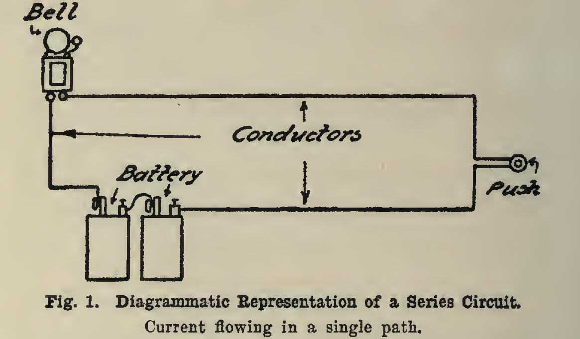
Series and Parallel Circuits When an electrical circuit is composed of a number of different parts, such as a bell, battery, push-button, and conductors connected as shown in Fig. 1, so that current flows in a single path, it is called a series circuit. The total resistance of the circuit is equal to the sum of the resist ances of the various parts. Suppose the bell has a resistance of 10 ohms, and the conductors a resistance of 2 ohms, then the total resistance of the circuit would be 10+2=12 ohms. The cur rent in all parts of the circuit is the same.
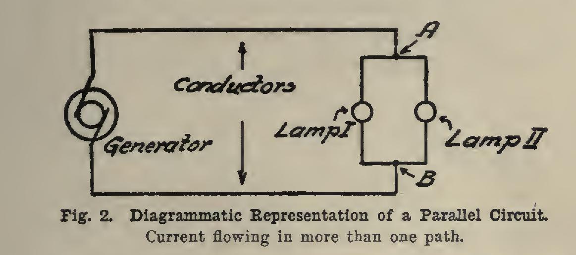
If the current in flowing from one point in a circuit to another has more than one path, we have what is called a parallel circuit. The points A and B in Fig. 2 are connected by two paths, one through lamp I, and another through lamp II. It is apparent that the resistance between two points is lessened as we increase the number of paths. If the resistances of all the paths are equal, the combined resistance is equal to the resistance of any path, divided by the number of paths. If the resistances are unequal, the total resistance must be calculated from follow ing equation: in which R equals the combined resistance; and etc., equal the resistances of various branches. This equation means that if you add together the quotients obtained by dividing unity by the various resistances, and then di vide the sum into unity, it will give you the com bined resistance.

The current in the main circuit is equal to the sum of the currents in the various branches. The currents in the branches are equal if the resistances are equal; otherwise, currents vary inversely as resistances; that is, as resistance diminishes, current increases, and vice versa.
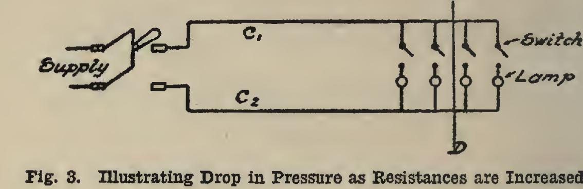
Let us assume a condition such as shown in Fig. 3, where there are a number of lamps ar ranged to be connected to a switch S through conductors and If the voltage at the switch is maintained constant at say 110 volts, the following conditions will exist as lamps are turned on: Before any lamps are turned on, the voltage at the end of the line is the same as the voltage at the switch; but as soon as the circuit is closed through the first lamp, a current flows in the line, and a portion of the 110 volts is con sumed in causing the current to flow in conduc tors and C2) thus reducing the voltage at end of the line. With increase in the number of lamps, the voltage to cause increased current to flow in the line is increased, resulting in a decrease in the available pressure at the end of the line. The pressure required to cause cur rent to flow in the line is equal to the resistance of line multiplied by the current; hence it is de sirable to have the resistance of the line as low as possible, in order to reduce this pressure to a minimum, since it represents a loss. This is an important consideration in the wiring problem, as we want the loss in the lines conducting the energy to the points of consumption to be as small as possible.
Size of Wire Required If the currents in the various branches of a circuit are known, the current in the main line may be obtained by adding them. Then, assum ing a certain loss in the line, say 2 per cent, and knowing the total length of conductor forming the circuit, we can calculate the size of wire required.
Suppose it is desired to conduct 10 amperes 100Cfeet with a loss of 2 per cent, the voltage of the line being 110. The total length of the cir cuit is 200 feet; the drop in voltage in the line is 2 per cent of 110=2,2 volts. Resistance=-2,2÷ 10..22 ohm. If .22 ohm is the resistance of 200 feet, then 1,000 feet, being five times as long, would have a resistance of .22 X5=1.1 ohms.
Referring to Table I, we find that a Number 10 wire has a resistance of .9785 ohm per 1,000 feet, which is next below this value. Tables II and III give sizes of wires to transmit a current of from 1 to 100 amperes in value over a conductor from 40 to 400 feet in length, with a 2 per cent loss.
The size of wire obtained from Tables EC and DI may conduct current with a 2 per cent loss; but its current capacity may not be sufficient. No wire smaller than a Number 14 shall be used, except for fixtures.
Table IV gives the current capacity for different sizes for both open and concealed work.
If the size of wire calculated from Tables II and III is smaller than that allowed in Table IV for a given current, the size in Table IV should then be used.
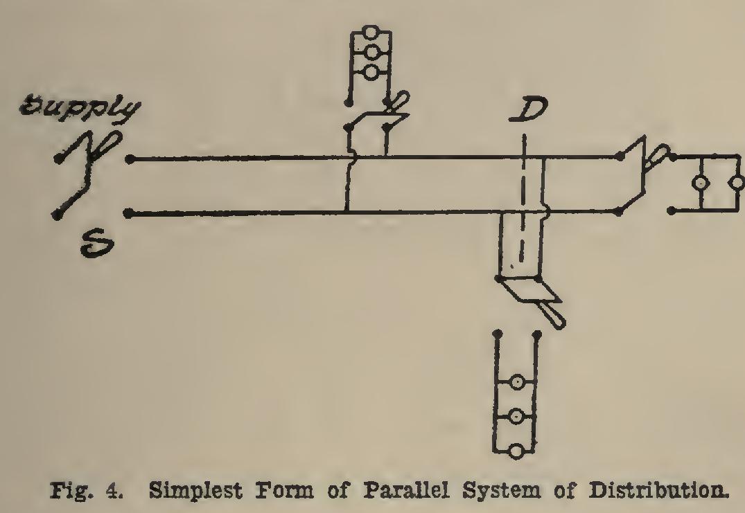
Systems of Distribution There are a number of systems employed in distributing electrical energy for lighting pur poses, the most important of which are the following: Parallel System. The parallel system in its simplest form is shown in Fig. 3. All the lamps are connected to the same two wires, and the current through each lamp is independent of the current through any of the other lamps. The length of conductors used in calculating the sizes for the wires would be twice the distance from the switch to point D, the most central point in the group of lamps. When this system is increased in size, it becomes more complex, as shown in Fig. 4. In this case there are branch circuits led off from main line to various parallel circuits. The length of conductor used in cal culating the size of wire for the main line is taken as the distance from switch S to point D, which is termed Center of Distribution of sys tem. The calculation for various branch cir cuits is the same as that for Fig. 3.
Multiple-Series System. The multiple-series system is shown in Fig. 5. The lamps are con nected in groups of two or more in series, de pending upon voltage between lines and voltage required to operate lamps, and these groups are connected in parallel. The total voltage be tween lines is distributed over the lamps in series. For example, if the voltage of the line is 220, and there are two lamps of equal resist ance in series connected to it, each lamp will have a difference of potential between its ter minals, of 110. This is the system employed in lighting street-cars where the voltage is ap proximately 550, five lamps being connected in series and ,constituting a single group. In this system it is impossible to have a single lamp operate by itself, as the current through any one lamp must pass through all the rest of the lamps of the same group.
Three-Wire System. The three-wire system of distribution is shown in Fig. 6, which con sists of two equal voltages connected in series. At the junction of the two machines, a third wire is run, which is negative with respect to A, and positive with respect to C. If lamps are connected to A and B, the voltage across them will be that of machine I, and current will flow on line A and return on line B. If, now, lamps are changed from A and B to B and C, the volt age across them will be that of machine 11, and current will flow out on B and return on C. It is seen that the current in C is away from the machines in one case, and toward them in the other. Hence, if the same number of lamps are turned on in both cases, the current in B will be zero, since the two currents neutralize each other. The output of this system is equivalent to two independent circuits, there being quite a saving in copper.