Concrete Mixers
drum, material, mixer, machine, feeder, plate, shown, box and corners
The "Standard" Mixer (Plate 9, lower figure) is a batch machine of the open-drum type. Its method of operation is clearly indi cated in the photograph. The mixing drum is tilted to whichever side desired, at an angle of about 45 degrees, and the material put in. With the rotation of the drum, the material is divided, and carried from the lower to the higher part of the drum, and returned again to the lower part, this operation being repeated during 25 to 30 revolutions of the drum. The operations of charging, wetting, and dumping are all per formed while the machine is in operation. When mixture is ready for use, the drum is tilted for ward far enough to either side desired, for the material to run out into the wheelbarrow or other receptacle placed to receive it. The interior of the drum is completely open to view and acces sible at all times, for cleaning, inspection of con tents, etc.
Street Paving Mixers.
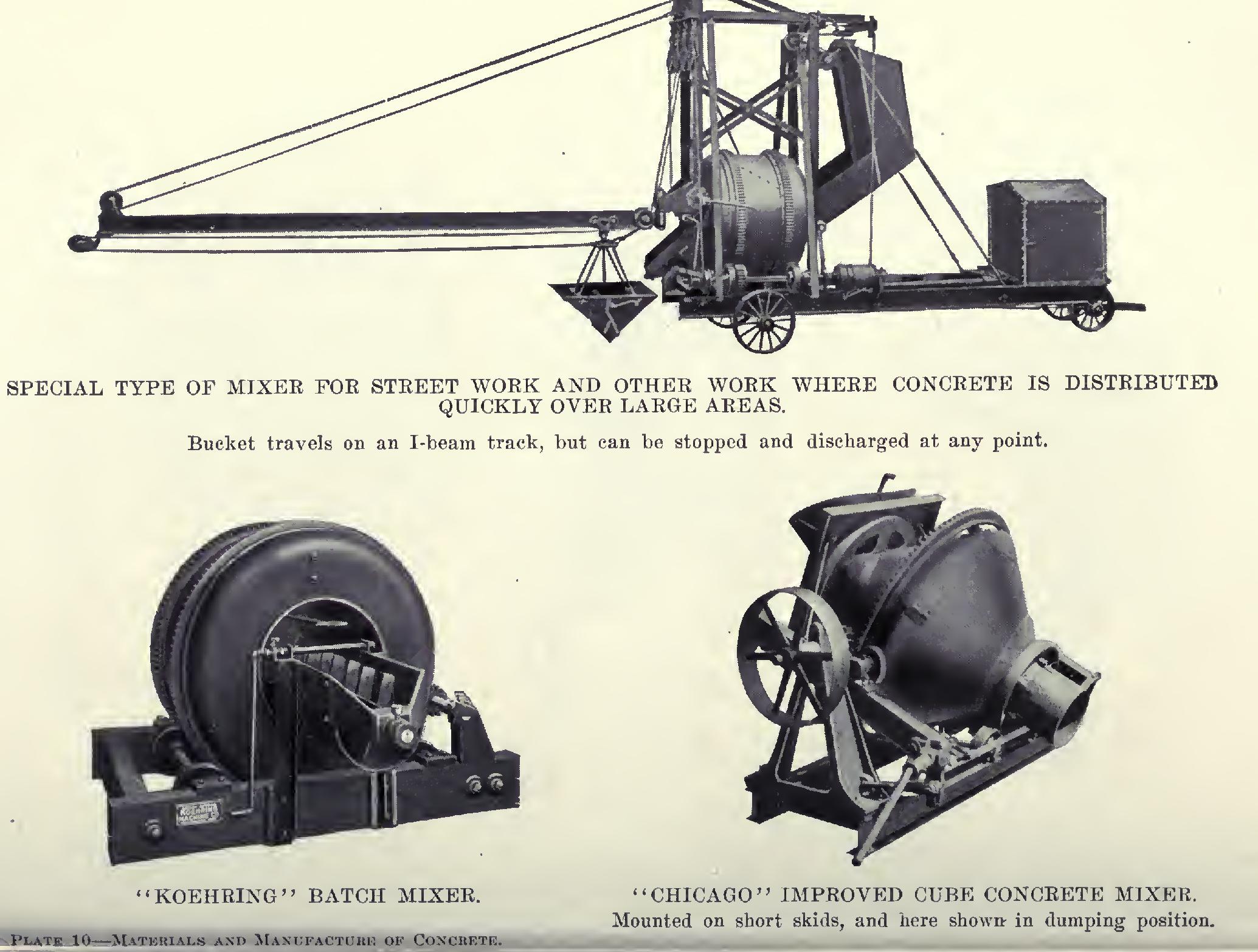
Under this head come a number of commercial types of machines de signed especially for laying concrete sub-base or footing for street paving, but adaptable to a wide range of work in which concrete has to be de posited rapidly over large areas, as, for example, in the construction of bridge abutments, retain ing walls, etc. A typical example of one of these machines is shown in Plate 10 (at top). They are usually equipped with an elevating charging bucket holding the full capacity of the drum, and an automatic water-measuring tank to furnish the right amount of water for each batch. The distributing bucket, self-dumping either by tilt ing or by bottom-dumping, travels on a beam track which may be 18 to 25 feet or so in length, and which swings horizontally through an angle of about 170 degrees, thus enabling an area up to 50 feet or so in width to be covered. The bucket can be stopped and discharged at any point.
Cube Mixers. One of the earliest types of rotary mixers developed consisted essentially of a cubical box revolving on a shaft passing through diagonally opposite corners, and fed and discharged through a door in one side. No de pendence was placed on interior disintegrator blades or scoops, the mixing being entirely the result of the motions imparted to the contents by the sides and ends of the box as it revolved.
This same fundamental principle is embodied in the "Chicago" Improved Cube Mixer, which is shown in Plate 10 (lower right figure). The old-time shaft is replaced with hollow trunnions riding on rollers and large enough to serve as openings for charging and discharging the mixer. The cube is rotated by gearing which meshes with the teeth on a circumferential rack fastened around the box or drum at right angles to and midway between the trunnions. An auto matic power-dumping device, which can be oper ated. by the man running the engine, is used in Fig. 20. "Clover Leaf" or Involute Curved Drum Concrete Mixer.

tilting the drum for discharge. Instead of the sharp corners of the old-style box, the corners are rounded, which gives a box of larger capacity in the same space and eliminates the opportunity for pocketing of the fine mortar.
"Clover Leaf" Mixer.
In this machine, which is of the rotary type, we have another example characterized by the entire absence of interior wings, blades, or deflectors to assist in the mixing process, dependence being placed solely on the peculiar shape of the drum and the series of movements it imparts to its contents.
The shape of the drum and the method of its operation are indicated in the diagram, Fig. 20. In section, as shown, the drum consists of a series of involute curves. These afford no angles or corners for the pocketing of material. As each curve is carried in turn to the bottom, it is instantly filled and covered by the falling charge. Continuing in its revolution upward, it rises out of the mass, cutting out and bringing up the bottom of the mass with it, and depositing it over the top with a scattering motion as it falls. The ends of the drum are made cone-shaped, also having involute curves, and these serve to cause a travel of the materials from the ends toward the center, where the corresponding curves in the straight part of the drum are constantly carrying up, cutting through, and turning over the entire charge. Discharge is effected by tilt ing the drum.
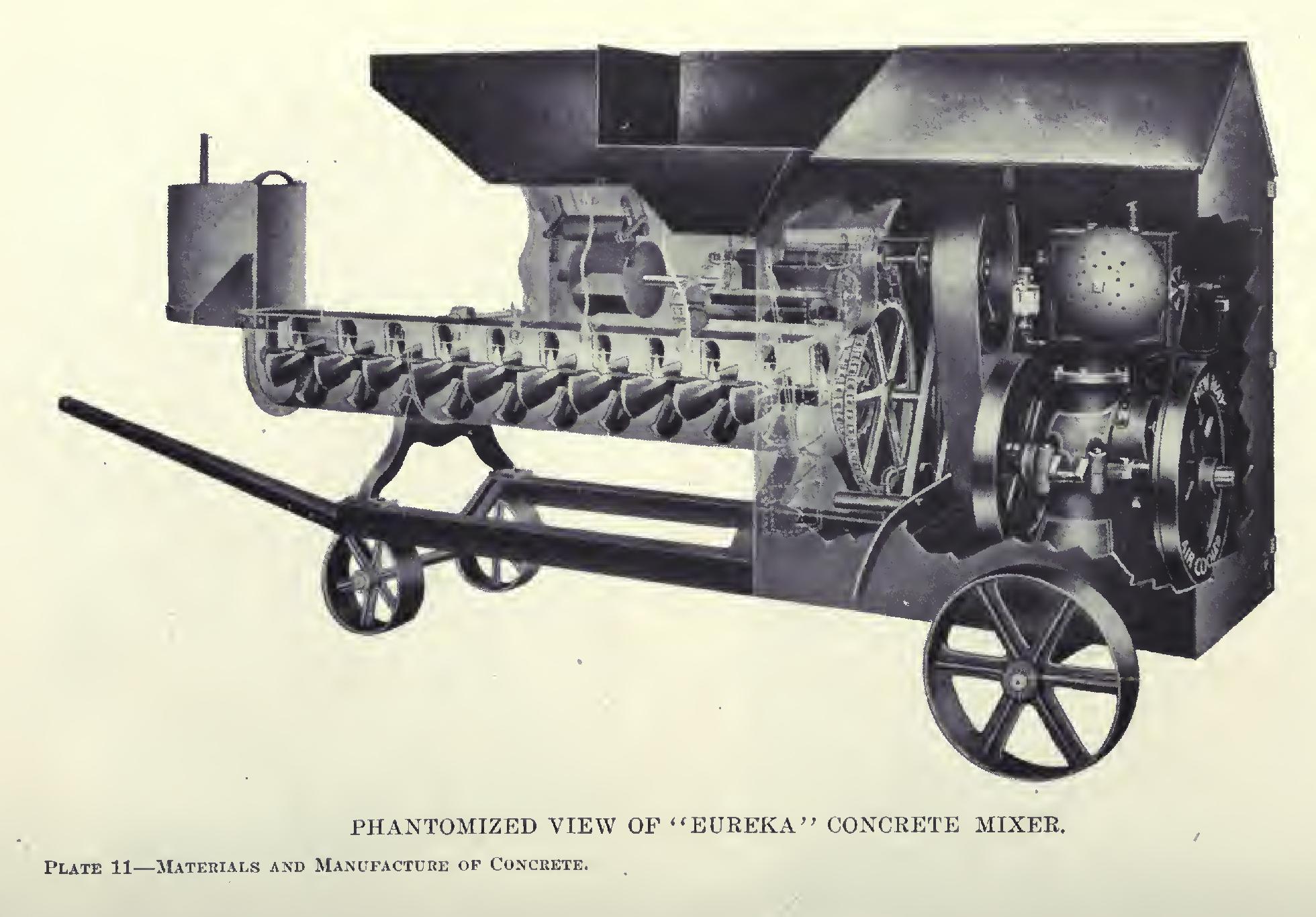
Among mixers of the continuous type, some are equipped with special devices for auto matically measuring the ingredients and feeding them to the machine in the proper proportions to give any desired mixture and consistency. The "Eureka" Mixer, of which a phantomized view showing details of mechanism is given in Plate' 11, is a machine of this type. The cement bin and feeder—the smaller one shown in the foreground—has a pocketed cylinder revolving between concave plates, opening into the hopper above, from which the pockets in the feeder are filled, and discharging directly into the mixing trough below. Back of this, is shown the feeder for sand and gravel up to 2-inch screen size. This is a similar cylinder to that used in the cement feeder, except that it is larger, and, in stead of being provided on the discharge side with a concave plate, is surmounted by a roller, held by springs. This serves to cut off the ex cessive flow of material, but provides sufficient flexibility to allow the rough, coarse material to be fed through the machine without catching. The feeder for crushed stone is a similar con struction on larger lines, to handle material up to 3-inch size. These several feeders can be quickly set to give any desired mixture. An agitator is provided in the sand bin to prevent damp sand from bridging over the feeder and stopping its action.