Crushers and Grinders
crushing, material, ring, rolls, crusher, type, jaw, shaft, jaws and frame
CRUSHERS AND GRINDERS In the processes of grinding and crushing, the expenses incurred through consumption of power, necessity for repairs, and delays result ing in loss of output, are ordinarily excessive. In the case of a grinder, the direct loss due to excessive wear of parts often results in a yearly cost for repairs amounting to from one-third to one-half the original cost of the machine. The efficiency of a good grinder, therefore, will de pend on its economy of power consumption, its compactness and strength of construction, and its capacity of output.
Plate 4 gives exterior and sectional views of the "Maxecon" Grinder. The mechanism and manner of operation are shown in the sec tional view. The underlying principle is that of a free, vertical, concave ring, yieldingly sup ported on three rolls pressing against its inner face, and having a free movement relative to one another. The lateral freedom of the ring allows it to adapt its position relatively to the material being ground, so that the line of least resistance to crushing of the material is automatically found, and the crushing, it is claimed, is accom plished with a minimum of wear and power.
As the ring revolves, the three rolls press against its inner face. These are the four wearing parts. The rolls are convex, and the ring is concave, and tracks on the rolls. The springs support the rolls yieldingly, and the rolls support the ring, so that the four crushing parts are free to move to pass iron or uncrushable ob jects, and are cushioned to take up shock and vibration and prevent crystallization or break age.
The feed falls onto the inner face of the ring. Centrifugal force holds it there in a layer an inch deep. It revolves with the ring, and passes under the rolls. The rolls are pressed by the springs outwardly against the material on the ring with a crushing pressure, adjustable by the screws to 20,000 pounds. The rolls roll over the material, crushing it against the ring. The crushed material flows off each side of the ring into the casing, and falls to the discharge.
The body of material between the rolls and the ring makes most of the material abrade on itself in crushing, thus reducing the wear on the wearing parts.

Fig. 16. "Mitchell" Crusher.
Crushers of the roll-jaw type are illustrated in Plate 5 (top figure) and in Figs. 16 and 18.
In the "Eureka" crushers of the "Mitchell" type (Fig. 16), the "Blake" type (Fig. 17), and the "Universal" type (Fig. 18), a special safety link-plate is provided for such cases of emerg ency as when unbreakable material is dropped between the jaws of the machine. Adjustments are very readily effected for greater or less fine ness of crushing, by means of the screw and hand-wheel, the angle of the link-plate being changed, thus adjusting the peculiar motion of the crushing jaw, which, being semi-rotary and at the same time reciprocating, facilitates the crushing of the hardest rock. Any degree of fineness, it is claimed, may be obtained—from Fig. 17. "Blake" Crusher.
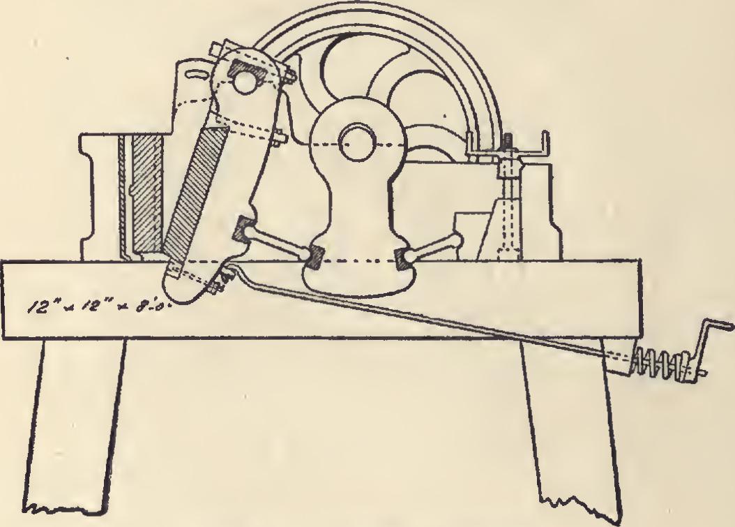
4-inch size in rock or clinker, hard or soft, to sand, at one operation, from the raw sizes to the fineness required in the processes of cement manufacture.
Roll-jaw crushers, in the small sizes, are fre quently of the pitman or heavy connecting-rod type; in the larger sizes, of the cam-and-roll type, the latter keeping the best adjustment under heavy wear and operating with the least vibration. The "Sturtevant" Crusher shown in
the top figure of Plate 5 is of the cam-and-roll type. It will reduce hard rock, through jaws set to one-fourth inch—that is, to sand size. Opposite the stationary front jaw is a long lever jaw backed by a toggle, which is rocked by a • Fig. 18. "Universal" Crusher.
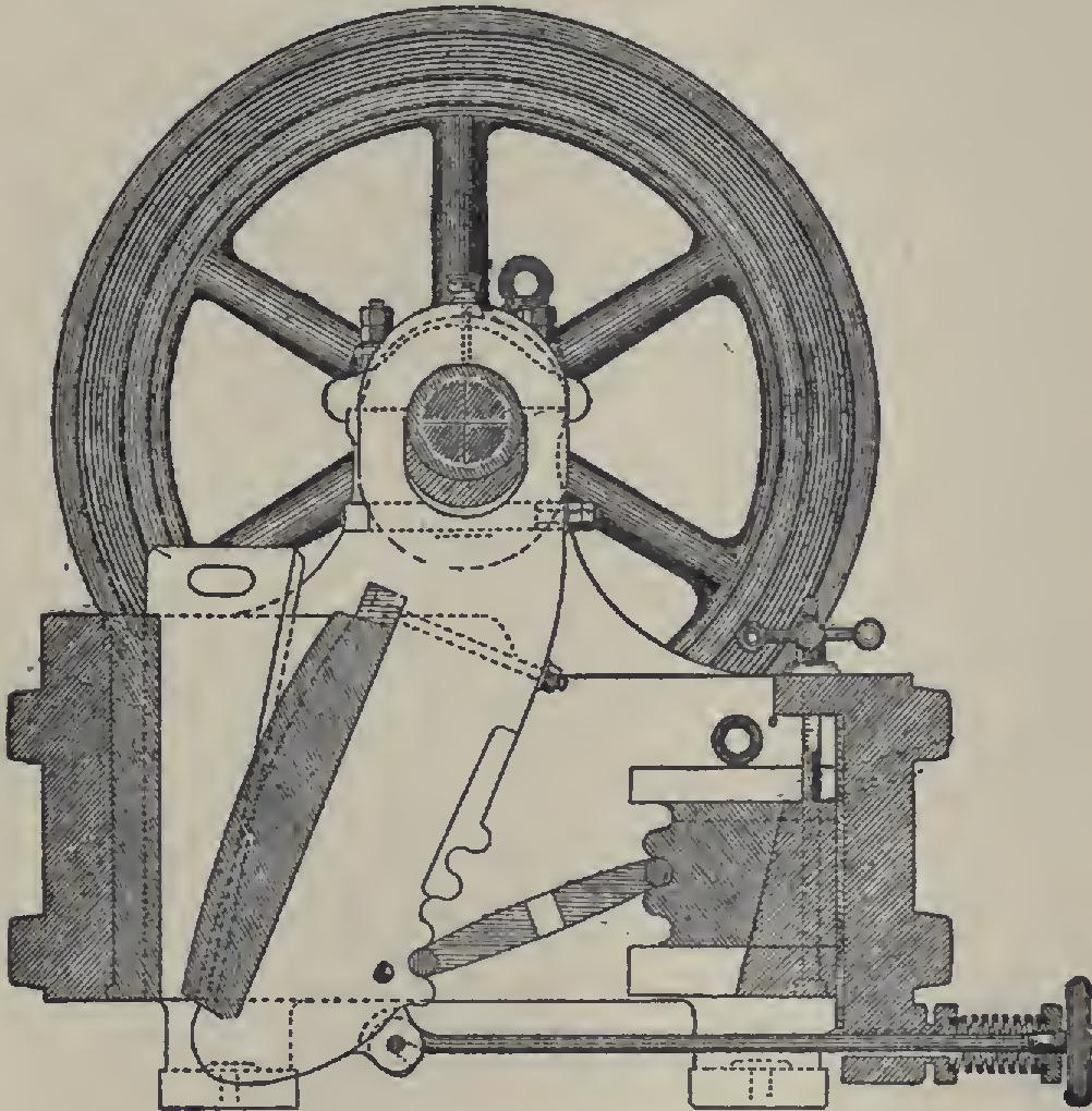
pitman connected with an eccentric cross-shaft. The jaws, although appearing to advance and recede, remain at a fixed distance apart, the rocking jaw face rolling upon the material caught between the jaws, and thus giving an action which is claimed to be remarkably smooth, regular, and powerful. The jaws are adjusted for fine or coarse work by a change of toggles, or by shims or thin plates back of the stationary jaw-plate. The massive rear casting charac teristic of this machine holds the plate as rigidly at the back as in the front, and is claimed to prevent deformation of the frame even under the severest conditions. This casting also carries the • driving shaft in bearings absolutely inde pendent of the frame, so that the shaft is un affected by the crushing stress and is always kept in alignment.
The "Hayden" Stone Crusher has its eccen tric shaft of forged steel extending out on each side to take 40-inch fly-wheels. The driving con nection is made to pulleys on each side, the size of which depends on the speed of the line-shaft running the crusher. The crusher jaws are ad justable so as to take in material one inch to ten inches in size.
In the "Koehring" Steel Stone Crusuher the band wheel is attached to an eccentric shaft upon which rests an anti-friction roller set in a lever. The fulcrum of this lever is at a low point on the crusher frame. The moving jaw is pivoted at the top end, and motion is imparted to it by means of a toggle which works in movable seats on the jaw and on the lever. By the employment of this simple principle, great power is given to the movement of the jaw.
Crushers are also of the gyratory type, the material being fed into a hopper with interior revolving and stationary mechanism. In the "Symons" Gyratory Crusher, a peculiarity of construction which is claimed to add materially to the strength of the frame is found in the sta tionary main shaft. The power is transmitted to the main head by means of an eccentric sleeve revolving around the main shaft, driven by bevel-gearing at the base, the resultant crushing movement, it is said, being uniform at all parts of the head.
Very frequently—especially where the quan tity of material to be crushed is large—crushed stone elevators are operated in connection with the crushing plant, to deliver the product di rectly to the stock pile or to dump-cars. They are adjustable to various heights by raising or lowering the long conveyor frame. They con sist in principle of a series of buckets carried on an endless chain or belt conveyor revolving on rollers, usually chain-driven, carried on a long, rigid frame.