
INSTRUMENTS, ELECTRICAL. On account of the great extension of electrical power supply, cable and radio teleg raphy and telephony, and research, electrical measuring instru ments have become extremely numerous of recent years ; and it is therefore desirable to preface a description of the leading types by a short summary and classification of their principles.
In order that an electric current should flow through a con ductor, there must be a potential difference, or P.D., usually ex pressed in volts, between its ends. The resulting current expressed in amperes always produces two effects : (a) an external magnetic field encircling the conductor and proportional to the current, and (b) an internal heating of the conductor due to agitation of its molecules which is proportional to the square of the current. If the conductor is a liquid compound or electrolyte, the passage of the current also produces a separation of its constituents or electrolysis, causing a liberation of gas or deposition of metal, the amount of which is proportional to the current and to the time for which it passes. All these three effects of the current have been employed as bases for its measurement. Conversely, the introduction of a magnetic field into a circuit (dynamo or transformer), or the heating of the junction of two conductors (thermopile), or chemical action (voltaic cell) causes an electro motive force to be set up, and electrical instruments based on these effects are in use. In addition when a difference of poten tial exists between two conductors there is an electrostatic attrac tion between them which can be used as a method of measuring the P.D.; and when electrified particles or electrons are projected across a vacuous space as in a valve tube they can be deflected either by electrostatic attraction or a magnetic field.
The steady current in a metallic conductor in amperes is equal to the P.D. in volts between its terminals divided by its resistance in ohms; and resistance measuring devices form a very important section of electrical instruments, with which are associated potentiometers for P.D. and current measurement. The power taken from or imparted to a circuit in Watts at any instant is obtained by multiplying the P.D. in volts by the current in amperes at that instant, and wattmeters enable this power to be directly indicated; while the energy consumed, generally meas ured in kilowatt hours or Board of Trade units (B.T.U.), is obtained by multiplying the power in kilowatts (I,000 watts) by the time in hours it is utilized, and is registered by energy meters; but if the supply P.D. is constant the product of the current and time or quantity of electricity is sufficient and is indicated by quantity meters.
Inductance and capacity are two electrical quantities which are of great importance in electrical circuits especially with high fre quency alternating currents. The former is the magnetic field which is linked with the circuit whenever a current flows through it, and therefore produces an e.m.f. whenever the current is increasing or diminishing, just as a mass resists acceleration or change of its velocity. The unit of inductance is termed the Henry (after the American physicist Joseph Henry, q.v.) and is such that it requires 1 volt to increase the current in it at the rate of 1 ampere per second. Capacity on the other hand has the opposite effect to inductance, as it offers infinite resistance to a steady motion or current, but allows alternating current to pass. It is the analogue of a spring which yields to changes of force, but remains stationary for a steady force.
Electrical and magnetic measurements are so closely related that they must be considered together, and we have to deal with magnetic force corresponding to electrostatic force, and magnetic flux corresponding to electric current.
The classification of electrical measuring instruments may be set out in the following table :— that the true ampere should deposit .00111828 gram per second.
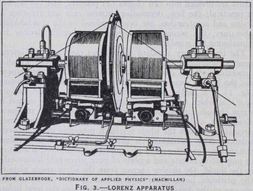
The best primary standard instrument for the determination of the ohm is that originally due to Lorenz in 1873. Essentially it consists of a metal disc (fig. 3) rotated steadily in the magnetic field of a coaxial cylindrical coil through which a current is passed. The arrangement is therefore equivalent to a "Faraday disc" in which the magnet is replaced by the current carrying coil, and an e.m.f. is induced between the centre and edge of the disc. If M is the coefficient of mutual inductance between the coil and disc (the magnetic flux through the disc for unit current in the coil), i the current in the coil, and n the number of revolutions per second of the disc, any radius of the disc cuts across the whole flux Mi in each revolution or Mni lines of force or Maxwells per second. This is, by definition, the e.m.f., E between the centre and edge of the disc. The current passing through the coil is also led through the resistance R to be tested producing a P.D.
The two primary electrical units are those of current (ampere), and resistance (ohm). From these can be derived the unit of potential difference (volt) and any one of these three can be deduced by Ohm's law from the remaining two. Standard instru ments are divided into two classes (a) primary, and (b) derived or practical; the first, demanding extreme care and accuracy in design and construction, are being confined to the standardizing laboratory, the second being convenient portable devices for reproducing the standard.
The two primary standard instruments employed at Govern ment standardizing institutions such as the National Physical Laboratory are the current balance for determining the ampere, and the Lorenz apparatus for determining the ohm. The former (fig. 1) is a highly accurate form of Kelvin current balance (q.v.) in which both the fixed and moving coils are wound in screw threads cut on marble cylinders of accurately measured dimensions, and the force on the moving coils due to current circulating through the whole system is measured by an accurate balance. This instrument is generally connected to a silver voltameter, consisting of a platinum bowl containing a solution of pure silver nitrate and a plate of pure silver held horizontally in the liquid. On passing current from the silver anode plate to the platinum bowl, silver is deposited on the latter, and the amount of the deposit can be found by weighing the bowl before and after the deposition. Such a silver voltameter constitutes the derived practical standard of current, and can be set up in any laboratory. The "International ampere" was defined by the Inter national Conference on Electrical Units and Standards in 1908 as "the unvarying electric current, which, when passed through a solution of nitrate of silver in water, in accordance with specifi cation II. attached to these resolutions, deposits silver at the rate of o•o0111800 of a gram per second." The more recent work of Dr. F. E. Smith at the National Physical Laboratory indicates V = Ri, and the ends of this resistance are connected through a galvanometer G to two contacts at the centre and edge of the disc. On varying the speed of the disc a speed can be found for which the galvanometer remains at zero, indicating no current in which case V = E, or Ri = Mni, so that R= Mn. The mutual inductance M is a constant of the apparatus which can be cal culated from the dimensions and number of turns of the coil and the diameter of the disc, so that when balance is obtained the resistance R can be determined by multiplying this constant by the speed, which is easily measured with accuracy.
The most recent form of Lorenz apparatus as designed and used at the National Physical Laboratory differs from the original form principally in having two discs and f our coils wound on marble cylinders so arranged (a) that the system is astatic or unaffected by uniform external magnetic fields such as that of the earth, and (b) that the magnetic field of the coils at the edge of the disc is very low so that small errors in the dimensions have less effect. As the e.m.f.'s in the two discs are in opposite direc tions two contacts only on their edges suffice. The convenience of this apparatus enables standard resistance coils to be standard ized directly, and this appears preferable and likely to be adopted in the future; but at present the practical derived stand ard is the mercury ohm consisting of a glass tube having a bore of I square millimetre in cross section and a length of 106.300 centimetres filled with mercury and at a temperature of o° C. As the cross section of the tube is always determined by filling it with mercury and weighing the latter, the practical definition of the ohm has been modified, and the International ohm is now defined as "the resistance offered to an unvarying electric current by a column of mercury at the temperature of melting ice, 14.4521 grams mass of a constant cross-sectional area and of a length of 106.300 centimetres." The mercury standard ohm is constructed by employing a glass tube having a perfectly uniform bore of i square millimetre cross section (1•129 mm. diameter) which is carefully calibrated for uniformity of cross section along its length by measuring the length of a known small volume of mercury as it is displaced to different positions along the tube. The tube is then cut and care fully ground to the required length and two additional short lengths of it have bulbs blown on their ends and are cemented in exact line on to the ends of the main tube, with very thin sheets of platinum foil between. The foil is then perforated so as to make a continuous uniform tube with contacts at the exact length apart. This tube is filled with pure redistilled mercury and cur rent is passed through it from bulb to bulb, while the P.D. between the platinum contacts can be balanced by a potentiometer and standard cell, thus giving the e.m.f. of the latter in terms of the ampere and ohm. Comparisons between the standard mercury ohm and a standard resistance coil can also be effected by a Kelvin double bridge. Whenever the mercury ohm is in use it is laid horizontally in a trough filled with melting ice. The testing cur rent must be only a small fraction of an ampere to avoid heating the mercury, on account of its somewhat high temperature coeffi cient of resistance (O•o9o% per I ° C) .

The mercury standard ohm is, however, far too difficult to construct to be of practical use, and consequently the standard resistances which are generally employed are in the form of platinum-silver or manganin coils carefully annealed and adjusted and standardized against the mercury standard at a standardizing laboratory. Many standard resistance coils have been devised, such as the original B.A. standard having a platinum-silver coil embedded in paraffin wax, the manganin standards of the Reichsan stalt and the more open forms of Fleming Burstall and Drysdale.
Having defined the ampere and ohm, the International volt is therefore defined as "that electrical pressure which, when steadily applied to a conductor whose resistance is one International ohm, will produce a current of one International ampere." As in the other cases a practical standard is desirable, and this is provided by a standard cell, of which the best and now uni versally used example is the cadmium cell first devised by Dr. Weston in 1892. This cell as now made consists of a small glass vessel of H form (fig. 2) having platinum wires sealed into the bottoms of the main tubes. At the bottom of one of them a small quantity of mercury is placed, and in the other some io% (by weight) cadmium amalgam.
Above the mercury there is a layer of mercurous sulphate and cadmium sulphate pastes, and above the amalgam, a layer of cadmium sulphate crystals. Some cadmium sulphate crystals are also placed over the above pastes, and the remaining space in the two main tubes and the connect ing tube is partly filled with saturated acidic cadmium sul phate solution, the upper ends of the main tubes being her metically sealed. In order to make the cell more portable by reducing the risk of displacing the contents, Dr. F. E. Smith introduced constrictions at the lower part of the tubes, these constrictions preventing move ments of the solid chemicals. The utmost care must be taken over the purity of the materials and cleanliness of the glass vessel and seals, and when the cell is made to the specification its e.m.f. is 1.0183 International volts at 20° C with a temperature coefficient of —0.004% per I ° C. The e.m.f. at any temperature t° C is given by the formula = E20 - 0.000,0406 (t- 20) -o.0OO,000,95(t- O•0OO,OOO,0I (t - The standard cadmium cell properly made up is the most accurate and convenient of all practical electrical standards, and measurements of any P.D. can be conveniently made with it, in conjunction with a potentiometer (q.v.). Another standard cell is the Clark cell. In this cell the cadmium of the Weston cell is replaced by zinc. The negative pole of a Clark cell consists of an amalgam containing io% of zinc; a positive pole, a pure mercury drop, covered with a mercurous sulphate paste; the electrolyte is a solution of zinc sulphate with excess crystals. In all other respects the construction of the Clark cell is similar to the Weston cell. The e.m.f. of the Clark cell at a temperature t° C is given by Watson as These can be divided into two chief classes : (a) Galvanometers or sensitive laboratory instruments for measuring very small cur rents, and (b) ammeters or indicating pointer instruments for large currents. The former are practically exclusively on the electromagnetic principle, while the latter are very diverse in form, and may be either electromagnetic or thermal.
gave a deflection of about 8,000 mm. per microamp. on a scale at t metre distance.
Improvements were made in the magnet system by Broca and Paschen and great improvement in sensitiveness and definiteness of zero was secured by employing the quartz fibres invented by Prof. C. V. Boys in 189o, but the most remarkable advance has been made quite recently by Prof. A. V. Hill and Mr. Downing at University college in conjunction with Dr. Daynes of the Cambridge Instrument company. Their galvanometer is similar to the Kelvin four coil instrument above described, but the magnet system has been made still smaller and of the recently discovered cobalt magnet steel (steel with 3 5 % cobalt) which has a much greater intensity of magnetization and permanence than any previ ous form of permanent magnet steel, while the mirror has been reduced to the smallest and thinnest dimensions compatible with optical efficiency. The needle system weighs only o.0045 grams and is suspended by a fine quartz fibre. The coils are also made much smaller so as to obtain the maximum magnetic field for a given resistance. The great obstacle to the general use of the moving magnet galvanometer has been its disturbance by stray variable magnetic fields such as those produced by electrical ma chines or tramways in the vicinity, as no system can be made sufficiently perfectly astatic as to prevent such disturbance, and attempts have been made to shield the galvanometer against such disturbances by enclosing it in heavy bells of soft iron, but with only partial success. Within the last few years however a new nickel-iron alloy (78 nickel to 2 2 iron) known as Permalloy or Mumetal has been introduced, which has a remarkably high permeability in weak magnetic fields, and it was suggested by Drysdale that this would enable an effective magnetic shield to be constructed with only a small thickness of this alloy. Acting on this suggestion Prof. Hill and Mr. Downing made a cylindrical mumetal case for their new type of galvanometer and found that the shielding was so perfect that the galvanometer was unaffected by the starting and stopping of a motor within a few yards of it. This important improvement has enabled the full sensitiveness of the galvanometer to be utilized without difficulty, and a i ohm galvanometer of this type with a periodic time of io sec. has given a deflection equivalent to 5o,000 mm. per microamp. on a scale at a metre distance, or about Soo times the equivalent sensitivity of the Kelvin galvanometer. This achievement may lead to the renewed popularity of the moving needle galvanometer which has been discarded in favour of the moving coil form owing to the freedom of the latter from magnetic disturbance.
The accuracy of the tangent galvanometer depends on the uni formity of the magnetic field of the coil in the neighbourhood of the needle, and this is only the case over a very small area. For this reason the magnetic needle should be as short as possible, but this is in itself insufficient, and a great improvement was made by Helmholtz who used two equal and parallel coils, separated by a distance equal to the radius of either (fig. 5). With this arrange ment and large coils very perfect uniformity of the field is se cured and the tangent law is very accurately followed. By a slight addition to the tangent galvanometer it can be used for the meas urement of current in another way which has certain advantages. The addition consists of mounting the coils and compass box on a rotatable vertical axis and providing them with a pointer which travels over a scale fixed on the base and divided in degrees. The galvanometer is first set up and turned till its needle is at zero (i.e., in the plane parallel to the coils and to the earth's field, as before) but when the current is switched on and the needle de flects, the whole system is turned round the vertical axis to follow the needle, until the zero of the compass box catches up with it. In this case the field H' of the coils rotates with, and is always perpendicular to them, so that when the zero catches up with the needle the galvanometer has been turned through an angle a such that for a single central coil. For this reason the galvanometer so used is termed a sine galvanometer, and the method has some advan tages as the needle is always in the same position as regards the field of the coils when reading, and the angle of rotation can be more accurately read on the fixed scale used for the coils. Although good tangent galvanometers can usually be used in either manner, the tangent principle has been more generally employed.

These sensitivities are far below those of the corresponding moving needle types, but the moving coil galvanometer has the great advantage of being undisturbed by outside magnetic fields, and of having constant sensitivity. On the other hand it has the disadvantage of being heavily overdamped on short circuit, and of being less suitable for very low P.D. measurements such as those on thermocouples, owing to the high resistance of its sus pensions. Up till recently the advantages in most cases heavily outweighed the disadvantages and moving coil galvanometers have consequently been in universal use for all but exceptional cases, but the introduction of the nickel iron magnetic screening by Prof. Hill and Mr. Downing may restore the moving needle instrument to favor.
Duddell Thermo-galvanometer.—Neither of the above types of galvanometer is of any use for alternating currents, and the great need for a sensitive alternating current galvanometer especially for radio measurements, led Duddell in 1904 to adopt the Boys radio-micrometer for this purpose. This instrument con sists in principle of a moving coil galvanometer consisting of a single loop of thin copper wire hung up by a quartz fibre between the poles of a magnet. The lower ends of this loop are soldered to two small vertical bars of bismuth and antimony which are soldered together to a small copper disc at their lower ends to complete the loop and form a thermo-junction. When heat radiation falls on this junction a current flows through the loop and deflects it, and Prof. Boys has used this instrument to meas ure the heat received from stars. Duddell utilized this instrument by fixing a "heater" consisting of a small length of Wollaston wire just under the junction, and the passage of a current through this heater warms the junction and deflects the coil.
Shunts.—The very high sensitiveness of reflecting galvanometers renders it frequently desirable to be able to reduce it by definite fractions so as to be able to measure larger currents, and this is effected by shunting the galvanometer. If a resistance of one ninth of that of the galvanometer is connected across the ter minals, of the total current passes through the resistance and only through the galvanometer, and if the resistance is that of the galvanometer, o or Tom respectively of the total current passes through it. Shunt boxes in which the requi site resistances can be converted by plugs are therefore often employed, but must be made for the particular galvanometers they are to be used with. In 1894, however, Profs. Ayrton and Mather devised a "universal" shunt box which could be used with galvanometers of a fairly wide range of resistances, and these universal shunts are now most commonly employed.
Vibration Galvanometers.—The great extension of bridge or null methods of testing inductance and capacity, etc., has cre ated a demand for highly sensitive galvanometers for alternating currents, comparable with those used for direct-current measure ments. None of the alternating current instruments so far de scribed in any way meet this requirement, and such measure ments have generally been made with telephones as detectors. This, however, confines the measurements to audible frequencies, and there are other objections to their use, so that vibration gal vanometers have come into favour. Such galvanometers are in principle direct current galvanometers of high and variable natural frequency and capable of being "tuned" into resonance with the supply, in which case they produce a vibrating streak of light on the scale and are exceedingly sensitive.
The first practical form of vibration galvanometers was that of Rubens (about 1895), which consisted of a vertical stretched wire carrying a magnet and mirror system and two coils like that of a moving needle galvanometer (q.v.) but non-astatic. By alter ing the tension on the wire and its length by two bridges like those of a monochord, the natural frequency of this system could be brought into unison or resonance with the alternating current in the coils, whereupon the spot of light on the scale broadened out into a long streak. This type was somewhat difficult to "tune." Duddell followed in 191 o by a vibration galvanometer on the lines of his oscillograph (q.v.), but with two long strips, a tension pulley, and two bridges which could be moved by a right and left handed screw. This instrument was remarkably sensitive and covered a frequency range from about 25 to 2,000 ,- per second, but was liable to respond to harmonics on the wave form. In 1911 Drysdale, with the help of Tinsley, devised a vibration galvanometer, primarily for use with his A.C. potentiometer (q.v.), in which the moving system was like that of Rubens, but mounted on a silk fibre. The control was exercised by a large horizontal permanent magnet, the strength of which could be varied by vary ing the distance between its pole pieces and by sliding an armature or "magnetic shunt" along it, so that tuning could be effected without touching the moving system. In 192o he substituted an electromagnet controlled from outside by a battery and rheostat, and this form has since been independently conceived and con structed by the Cambridge Instrument company. Moving coil variable bifilar suspension vibration galvanometers of great sensi tivity have been introduced by Campbell, Gall and others, while a most ingenious single fibre unbalanced instrument has recently been devised by Prof. Moll. All such instruments are extremely sharp in their tuning, and therefore require the frequency of the supply to be kept constant to within about o• i % for their satis factory use.
Oscillographs and String Galvanometers.—The extensive employment of alternating currents of all frequencies from 25 to thousands or millions of cycles per second has caused a great demand for instruments which will give a record of the variation or wave-form of such currents, just as the steam or gas engine indicator records the variations of pressure in the cylinder, and these instruments are known as oscillographs. Prior to their intro duction, such wave forms were somewhat laboriously determined by an instantaneous contact method originally devised by Joubert, and the Hospitalier "Ondograph" based on this principle enables the form of the wave to be automatically traced on paper by a pen. But such methods can only deal with currents which vary in the same manner over some seconds or minutes of time, while the true oscillographs will deal with transient currents which may last only a few hundredths of a second.
Oscillographs are, therefore, galvanometers capable of following rapid fluctuations in the current, and may be either of the moving needle or moving coil type. The inertia of their moving systems must be as low as possible, their natural frequency of oscillation very high, and their damping as nearly as possible critical. For these reasons, the moving system must be as small and light as pos sible. Blondel in 189 i devised the first oscillograph on the moving coil principle, and was closely followed by Duddell who in produced the form of oscillograph which has since been most largely used in this country. In order to diminish the inertia of the coil to a minimum it was reduced to a single loop of fine phosphor bronze strip, and as with even this small inertia a large control was found necessary to obtain the high natural vibra tion frequency aimed at (i o,000 — per sec.) , the two upper ends of this loop were attached to the terminals and the lower portion passed over a small ivory pulley which was pulled downward by a spring, so that both sides of the loop were equally strained nearly up to their elastic limit. The loop with its pulley and terminals was mounted on a brass plate and could be mounted between the poles of a powerful electromagnet, taking the place of the perma nent magnet of the d'Arsonval moving coil galvanometer (q.v.). In order to obtain the strongest possible magnetic field iron pieces were fixed on both sides of and between the strips, and for observ ing the deflections a very small thin rectangular mirror was ce mented across the two strips at their centre. Damping was secured by closing the front by a glass plate and filling the space with oil. On passing current round the loop, one strip moved transversely forward and the other backward in the gaps, so that the mirror was tilted sideways and deflected a beam of light pro jected on to it by an arc lamp. By suitable optical arrangements the reflected beam was focussed on to a photographic plate or film which could be dropped or driven vertically downwards, and the variations of current in the loop were then recorded as a wave on the film.
In order to enable the wave form of a constantly alternating current to be seen or projected on a screen, Duddell also intro duced a second mirror caused to oscillate in a direction perpendic ular to that of the first mirror, by a cam driven by a synchronous motor from the alternating supply mains. The reflected beam from the oscillograph mirror was caused to fall on this second mirror and then on to the screen, causing the wave form of the current to be exhibited as a continuous picture, owing to the persistence of vision.
In nearly all alternating current investigations it is desirable to have simultaneous traces of the variation of the current and the P.D. and for this purpose Duddell employed two loops side by side in the same magnetic field with an iron plate between them to keep the field as strong as possible. One of these loops carried the current to be recorded or was connected across a low resist ance so as to shunt a fraction of the current when it was too large for the strip; while the other was connected, in series with a large non-inductive resistance, across the circuit so that the current through it was proportional to the P.D. at each instant. Each of the loops was provided with mirrors and a third "zero mirror" was arranged between them, so that when the light from the arc fell on them three beams were reflected, giving the P.D. and current waves and the zero axis respectively.
Portable oscillographs on this principle have recently been intro duced by the Westinghouse company in America and the Cam bridge Instrument company in England, the vibrators being made up as separate elements each with its own permanent mag net, and the illumination being produced by a metallic filament lamp which is temporarily overrun during exposure of the film. For high voltages the electrostatic vibrator of Ho and Kato is often substituted for one or more of the vibrators in the outfit.
An ingenious oscillograph on the hot wire principle was devised by J. T. Irwin in 1907, but has not come into general use. In France, M. Dubois has recently devised an oscillograph of the soft iron type in which a tongue of soft iron is caused to vibrate be tween the poles of a permanent magnet, and communicates its motions to the mirror through a strip and pulley.
The Einthoven galvanometer is, unfortunately, very costly, owing to the difficult construction of its poles and optical observ ing arrangements, and an ingenious attempt at securing its ad vantages with the ordinary simple reflecting mirror device has recently been made by Mijnheer van Dyck of Leyden in his "Torsion String" galvanometer. In this galvanometer the fibre is of the finest silicon bronze wire, and a second thin wire of hard drawn copper lies close to and parallel to it over the portion be tween the magnet poles and is soldered to it at its top and bottom. As the copper wire is of much lower resistance than the central bronze wire, the bulk of the current flowing down the latter is shunted into the copper wire which, therefore, becomes a moving coil with half a turn, and tends to rotate round the central wire, being controlled by the torsion of the latter. As the system is unsymmetrical and therefore unbalanced, a strip of aluminium foil is cemented across the two wires at their centre and a small silvered mirror is cemented on this strip on the opposite side so as to balance the loop, a cleft being made in the corresponding magnet pole to allow of its free rotation. This galvanometer can be used with the ordinary lamp and scale, and with a resistance of Io ohms and periodic time of o.oi sec. is stated to give a deflec tion of 3 mm. per microampere at i metre, which is nearly equiva lent to the sensitivity of the Einthoven galvanometer.
The above type of oscillograph has the advantage of being permanently evacuated, but it is only suitable for the observa tion of certain cyclic phenomena, and does not permit of the photo graphic recording of intermittent or transient ones. Prof. Dufour in France and Dr. A. B. Wood in England, have therefore pro duced cathode ray oscillographs in which photographic plates can be inserted, and by using a cold cathode with a P.D. of 50,000 volts the former has obtained records of the wave form of radio transmitters up to over i,000,000 — per second. Such oscil lographs require to be evacuated after the removal of the camera or photographic plate, and not being hermetically sealed, are kept continuously evacuated during use.
(b) Moving Coil Permanent-magnet Indicating Instruments were introduced by Dr. Weston in 1888 and were similar to the d'Arsonval galvanometer, except that the coil was pivoted and controlled by spiral springs carrying the current, and a pointer was substituted for the mirror. This type has been developed into the most accurate of all direct current indicating instruments in the Weston and other laboratory standards, and has assumed many different forms, notably the "Cirscale" instruments of Messrs. Record, in which the poles are so arranged that the coil and pointer can rotate through nearly 2 7o°. As the thin control springs can only carry a very small current (7 5 milliamperes is the usual maximum) the instrument can be used as a voltmeter by connecting a high resistance in series with the coil, but if it is to be employed for measuring larger currents, "shunts" are provided consisting of manganin or constantan strips having two terminals through which the current is passed, and two other terminals to which the instrument is connected, so that it acts as a low reading voltmeter measuring the current by the P.D. across the shunt. A single moving coil instrument with a set of series resistances and shunts will therefore serve for a very wide range of P.D. and current measurements, and portable "test sets" are commonly made covering the range from about o.i to 600 or more volts or amperes.
The moving soft-iron instruments are of great value in principle as they are not only simple in construction but are equally suitable for direct or alternating currents, as they obviously indicate the square root of mean square (R.M.S., or effective) current; while the moving coil permanent magnet instruments will only read on continuous current. Until quite recently, however, this valuable property was not taken full advantage of, owing to certain appar ently inherent defects in the type. The first is the want of pro portionality of magnetization in the iron to the current, and the hysteresis in the iron, which causes the instrument to read higher for a certain current when it has fallen from a higher value, than when it has risen from a lower one. In addition there is the high inductance of the coil with its iron cores, which causes a volt meter of this type to read lower for the same P.D. as the fre quency is increased and prevents the use of shunts for ammeters; and lastly, the demagnetizing effect of induced eddy currents in the iron and any metal parts close to it. All these errors have mili tated against the adoption of this type as a universal instrument, although A.C. ammeters and voltmeters for a single frequency have been largely employed.
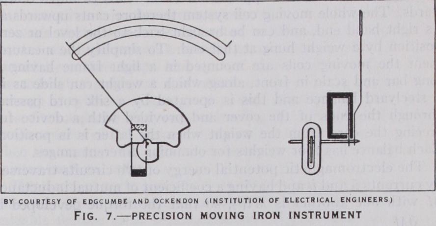
Within the last few years, however, a great advance has been made notably by the substitution of Permalloy or Mumetal for the moving iron, which has resulted in the practical elimination of wave form and hysteresis errors, and by making the coil as small and flat as possible so as to allow of a thin plate of this alloy to be attracted into it, thus greatly reducing the inductance and eddy-current errors. It was pointed out by Drysdale in 1924 that since the electromagnetic energy in an inductive coil E = where L is its inductance and i the current passing through it, the torque T = = Zit aL , so that the instrument always oper ae ae ated by the increase of its inductance from at zero to at its highest reading; and he proposed the term "electromagnetic efficiency" for the fraction On examination of existing instruments it was found that this efficiency was only 1 or 2% or less, so that of the total inductance about 99% was useless and noxious, and only about 1 % useful in deflecting the instru ment. Acting on this principle Col. Edgcumbe and Mr. Ockenden devised an ammeter on the lines above indicated (fig. 7), with the result of obtaining practically negligible hysteresis and eddy current errors and of increasing the electromagnetic efficiency to about 30%, and the current range to 15 or 20 fold. This has enabled it to be employed with shunts or series resistances like the moving coil instruments, either for direct current or with alter nating currents up to 200 periods per second. It is claimed, and with apparent justice, that such instruments need not be inferior in accuracy to moving coil or other high-grade instruments. By using one fixed and two independently moving irons, Record has produced a moving iron instrument having a scale covering about 270°.
The principle of the Kelvin balance is shown in fig. 8. The instrument consists essentially of six horizontal coils, four of which are fixed (F) and two movable (M), and the current to be measured traverses the whole of the coils in series. In order to allow the two movable coils to swing freely between the fixed ones, they are suspended by a large number of straight fine wires forming straight straps or ligaments. The current passes round the coils as shown by the arrows, and it will be seen that on the right hand side the current in the centre moving coil is in the same direction as that in the upper and in the opposite direction to that in the lower of the fixed coils. The moving coil is therefore attracted to the upper and repelled from the lower coil and tends to move upwards, while the left hand moving coil in which the current circulates in the opposite direction tends to move down wards. The whole moving coil system therefore cants upwards at its right hand end, and can be brought back to the level or zero position by a weight hung at that end. To simplify the measure ment the moving coils are mounted in a light frame having a long bar and scale in front, along which a weight can slide as in a steelyard balance and this is operated by a silk cord passing through the ends of the cover and provided with a device for freeing the cord from the weight when the latter is in position. Each balance has four weights for obtaining different ranges.
The electromagnetic potential energy of two circuits traversed by currents and and having a coefficient of mutual inductance M with one another is so that the torque developed is In the Kelvin balance the two circuits are in series so ae that i, and the torque is i2 or is proportional to the ae square of the current, so that the instrument serves equally for direct or alternating current measurements. Various sizes of these balances, "Centiampere," "Ampere," "Deka-Ampere," "Hector-Ampere," and "Kilo-Ampere" have been constructed, but the latter, on account of their large conductors, are not ac curate for high frequency currents owing to eddy currents, although the conductors are stranded or laminated.
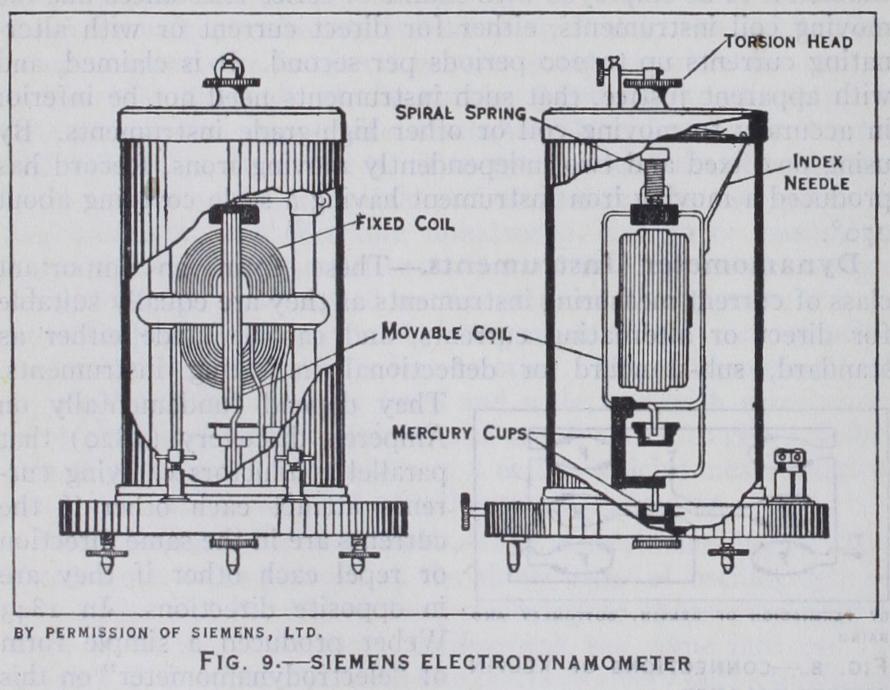
The Siemens dynamometer (fig. 9) was for many years the most useful form of substandard instrument for both direct and alternating current testing. It consists essentially of two coils at right angles, the inner (F) having a large number of turns and being fixed with its axis horizontal on a wooden frame, and the outer (D) in the form of a loop encircling the fixed coil and suspended by a silk thread, with its two ends brought out at the bottom to dip into two mercury cups MM. On the top of the frame a circular scale is fixed, with a torsion head T and pointer, a cylindrical spring S encircling the suspension being mounted between the torsion head and the top of the coil. The current circulates round both coils in series and causes the swinging coil to turn, whereupon the torsion head is turned until the torsion of the spring brings the coil back to its zero position as indicated by a pointer I fixed to the top of the coil. The current then= KVD, where K is the constant of the instrument and D the angle turned by the torsion head. In order to increase the range of the instrument, the fixed coil is generally made of two portions with different thicknesses and number of turns of wire, and either of these can be connected in series with the moving coil.
Both of the above instruments are of the standard type in which it is necessary always to bring the coils into the same position, in order that the theoretical square law shall be followed. But deflectional direct indicating instruments can be made by simply providing the moving coil with a pointer and control spring, in which case they are equivalent to permanent magnet moving coil instruments in which the magnet is replaced by the fixed coil. In 1890 the first instrument of this type was introduced by Dr. Weston as a dynamometer voltmeter, the fixed and moving coils being circular, wound with fine wire, and connected in series through the spiral springs which provided the control. A high non-inductive resistance was connected in series with the combina tion and the instrument was graduated as a direct reading volt meter. Additional ranges were provided by extra series resistances. Dynamometer ammeters have also been constructed by making the fixed coil of thicker wire and connecting the moving coil in series with a small non-inductive resistance across the terminals of the fixed coil or an additional shunt, but it is difficult to elimi nate inductive errors sufficiently in such instruments.
The most valuable application of the dynamometer principle is to standard and deflectional wattmeters, and to energy meters, which will be described later.
Induction instruments may be divided into three main classes, (a) repulsion, (b) shaded pole and (c) double pole instruments. The first depend upon the repulsion effect first discovered by Prof. Elihu Thomson, that a metal disc or ring is repelled from an electromagnet excited by alternating current. The explanation is that the magnet induces an e.m.f. in the disc or ring in quadra ture with the magnetic field, which consequently produces eddy currents in it. If these currents were in phase with the induced e.m.f. they would also be in quadrature with the magnetic field and there would be no resultant force, but owing to the inductance and low resistance of the disc they lag behind the e.m.f. and be come somewhat in antiphase with the magnetic field, producing a resultant repulsion.
The simplest application of this principle to ammeters is that of the Westinghouse company, in which the moving element con sists simply of a thin aluminium or copper disc on a pivoted spindle perpendicular to its plane. The edge of this disc is how ever cut in the form of a cam and can turn in the gap of a' laminated electromagnet through the coil of which the alternat ing current to be measured is passed. A control spring and pointer is attached to the spindle and when the system is at zero the whole of the pole face is covered by the disc. When the current is passed the repulsion effect causes the disc to turn so that less of the pole face is covered by the disc, and by suitably shaping the edge a long and fairly even scale can be obtained. In order to damp the swinging of the disc, a permanent magnet is mounted on the other side of it, which retards its movements by the eddy currents induced.
The shaded pole type of instrument is next in simplicity of construction, but is best understood by first describing the double pole form. If two laminated electromagnets A and B are fixed close together and act on a single circular disc, the alternating magnetism of A induces currents in the disc part of which pass through the gap of magnet B, so that the disc behaves as a mov ing coil carrying current derived from A and traversing the mag netic field of B, and thus producing a torque. But, reciprocally, the currents induced in the disc by magnet B traverse the field of A, and it is fairly obvious from the symmetry of the arrange ment that if the two magnetic fields vary in the same phase, there will be no resultant torque, as there is no reason why it should move from A to B rather than from B to A. But if the magnetic field in B lags in phase behind that of A there is a resultant torque from A to B and this torque is proportional to sin4) where and are the currents in the two coils and 4 the angle of phase different between the fields. This difference in phase may be secured in several ways, e.g., by shunting one of the mag nets or connecting it in series with a condenser, or by supplying the currents from different parts of the circuit, as will be described under wattmeters and energy meters.
The most simple application of this principle however to cur rent measuring instruments is by "shading" part of a single pole (fig. 1o). If a single laminated electromagnet has a cleft in its pole and a thick copper ring C encircles one part of it, B as shown, the eddy currents induced in this ring by the magnet react on its field and cause the magnet ism of the part of the pole en circled by the ring, or "shaded" portion, to lag behind that of the remainder or unshaded portion A. Thus the single magnet be haves like the two magnets above referred to, and a pivoted disc arranged in the field of this magnet tends to turn from A to B. By adding a spring and pointer and damping magnet, a useful form of ammeter can be produced, and the scale can be of any length up to nearly 36o°. The theory of induction instruments is very complex, and they are liable to many errors, but by careful design they may be made very useful and accurate instruments.
Current and P.D. Transformers.—A great difficulty with al ternating current instruments is their lack of range, as since the forces in them are generally proportional to the square of the current, a reduction of the current to one-third reduces the force to one-ninth of its maximum value, and many instruments there fore only have about a fourfold useful range. On the other hand, the range of currents and voltages to be measured is enormous, from fractions to tens of thousands of amperes or volts. With nearly all such instruments shunts are useless owing to the in duction errors they introduce, and for many years past the prac tice of employing transformers has been adopted. If a trans former is made with a good well-laminated magnetic circuit and two coils wound close together, one of which is short circuited through an ammeter, while the other has the alternating current to be measured passed through it, the current induced in the secondary coil will be proportional to that in the primary coil and approximately in the ratio of the number of turns in the coils. For example if an alternating current of 5,000 amperes is to be measured, a transformer may be made with a single bar or turn carrying this current, and a secondary coil of r,000 turns which is connected to a 5 ampere ammeter. This device has the further important advantage of isolating the ammeter completely from the main circuit, which may be at a dangerously high poten tial on modern supply circuits. In like manner, if a transformer is wound with two coils of fine wire, one having ioo times as many turns as the other, and an alternating P.D. of io,000 volts is applied to the coil having the larger number of turns, it will in duce zoo volts in the other coil which can be measured in an ordinary voltmeter, without connecting it to the high voltage cir cuit. By the use of the Mumetal for the iron of the transformers, Col. Edgcumbe and Mr. Ockenden have recently made instru ment transformers of very high precision.
Thermal or Hot Wire Instruments.--These instruments, as has been mentioned, depend upon the heating effect of a cur rent passing through a conductor, and are equally suitable for direct or alternating current measurement. The power developed in a circuit having a resistance r ohms and carrying a current i amperes is yip watts, and produces a heating effect of 0.24 ri calories per second. Since the heating is proportional to the square of the current, it is the same for either direction of flow, and the average heating with alternating current is proportional to the mean square of the current.
Hot wire instruments are of two types (a) expansion and (b) thermo-junction. In the former the linear expansion of the wire caused by the heating is utilized ; in the latter the heat is com municated to a thermo junction, which is connected to a milli voltmeter.
Until the last few years hot wire instruments have all been on the expansion principle, the earliest form being the voltmeter, devised by Maj. Cardew in 1883. In this instrument a long thin platinum-silver wire was strung over pulleys in a brass tube, and the ends of the wire were connected to the terminals; while the pointer was mounted on a spindle geared to a pulley which was turned by a thin strip. One end of this strip was attached to the axle of a pulley at the centre of the wire and the other, through a cylindrical spring, to a fixed support. When current passed through the wire, causing heating and expansion, it yielded to the tension of the spring and caused the pointer to turn; while when the current was broken, the wire contracted and pulled the pointer back to zero.
This form of voltmeter was very clumsy and inconvenient and wasteful of power, but its freedom from inductance was such a valuable feature as to stimulate improvements, and modern hot wire instruments have been constructed on the "sag" principle originally suggested by Ayrton and Perry, but first carried into execution by Hartmann and Braun. In these instruments the heated wire is straight and only a few inches long, and both ends are fixed; but the strip attached to the pointer and antagonistic spring is attached near the centre of the wire, so that the tension tends to pull it to one side or cause it to sag. A very small in crease of the length of the wire will greatly increase this sag, and approximately as the square root of the extension, so that not only does this method give a large magnification, but it helps to compensate for the natural square law of the expansion, and gives a more uniform scale. The magnification secured by a sin gle application of this principle was, however, hardly sufficient, so that in the Hartmann and Braun instrument (fig. r z) the transverse wire S2 was again treated as a sagging wire and the strip actuating the pointer was attached to its centre, making it what may be called a double-sag instrument. A thin aluminium sector passing between the poles of a permanent magnet served to damp the indication. An average instrument of this type takes about 0.2 ampere at its maximum reading and has a resistance of about 17 ohms, implying a power consumption of 0.7 watt in the wire; but when used as a voltmeter for 120 volts it consumes a total of 24 watts, as compared with only 4 or 5 watts for moving iron voltmeters. To adapt this type of instrument as an am meter, one method is to lead the current in and out of the wire at several points by means of very thin and flexible strips and S3. If the current is led in at the centre of the wire and out by its two ends the range is doubled, and so on. For still heavier currents a large number of exactly similar wires can be con nected in parallel, and shunts can also be employed.
Expansion instruments have done valuable service for alter nating current measurements, es pecially at high frequencies, but they have never attained the ac curacy of good electromagnetic instruments, owing to the changes of zero due to expansion of the supports. Various methods of compensation have been devised with good results, but none have been completely satisfactory under all conditions. Another ob jection to them is their very small overload capacity, as the wire must be raised to a high temperature to obtain sufficient expansion. Doubling the current produces four times the heating effect. Fusing of the working wire involves remounting and recalibration of the instrument.
The thermo-junction instruments which were first put into commercial form by the Weston company are much more con venient than the expansion type, and are probably destined to supersede it, as they only involve a simple attachment to a stand and type of moving coil millivoltmeter. For many years before their advent a very common laboratory device for measuring high frequency currents was the `'crossed thermo-junction," consist ing of two fine wires, one of copper and the other of constantan (nickel-copper alloy) crossed at right angles and soldered together at their crossing point. Current was passed from one end of the copper wire through the junction to one end of the constantan wire, causing the junction to be heated; while the other two ends were connected to a moving coil galvanometer. As the thermo e.m.f. of such a junction is about 4o microvolts per degree, a rise of 300° C produces an e.m.f. of 12 millivolts, which will produce a reasonable deflection on a moving-coil pointer instrument. The Weston company therefore employed one of their standard forms of moving coil millivoltmeter with a recess in the base in which a strip carrying a short heating wire and thermo-junction was clamped. This can be easily replaced if burnt out.
Dr. Moll has recently greatly improved on this device by what he calls his "thermo-converter," having a fairly long heating wire threaded through about 5o insulated thermo junctions. By this means he secures a thermo e.m.f. of 8.5 millivolts for 16 milli amperes in the heating wire and a rise of temperature of only To° C, which allows a very ample margin for overload.
The principle of the electrodynamometer wattmeter was first put forward by Ayrton and Perry in 1881, and was adopted by Kelvin in his Watt balance, and by Siemens in 1884, the moving coils of the Kelvin balance or Siemen's dynamometer being made of fine wire and in series with non-inductive resistances. Unfortunately, Ayrton and Perry, from a theoretical considera tion of its behaviour on alternating current circuits at various power factors, were led to the conclusion that large and indeter minate errors would appear at low power factors (i.e., large angles of lag or lead of the current), and as this was apparently con firmed by some tests with a defectively constructed wattmeter of Swinburne's, the dynamometer wattmeter fell into disrepute. It was not till Igor, when Drysdale gave a different treatment of the errors, and showed that they could be made perfectly deter minate, and be reduced to inappreciable proportions by suitable design, that confidence was restored. He showed that if the ratio of resistance to inductance of the shunt circuit was over 300 ohms per millihenry, and if the instrument was kept free from metal other than the carefully stranded coils, no readable error could exist, and produced a wattmeter in which these require ments were fulfilled. A little later Duddell and Mather produced an astatic wattmeter on very similar lines. Both of these instru ments were of the torsional or standard type, and their current ranges could be varied by combining the strands of the current coils in various series and parallel combinations, while the P.D. range could be extended to almost any extent by series resistances.
Deflectional direct reading dynamometer wattmeters have been devised by Kelvin, Heap, Hartmann and Braun, the Weston In strument Company, and many others, and are similar to the cor responding forms of dynamometer voltmeters, but with the fixed coils wound with thick wire to carry the current. The Weston wattmeter has a circular formerless moving coil fixed on a pivoted spindle with two spiral springs serving as control and leading-in wires, and a light truss-form pointer at the upper end, and damp ing vanes at the lower end. Two fixed current coils are held in a frame of high resistance metal alloy to reduce eddy currents, and the moving coil swings inside them over an arc of about 90°.
The quadrant electrometer can also be used as a wattmeter since the deflection is proportional to the product of the P.D. between the quadrants and of that between the needle and the mean of the quadrants or to (V — Vl+ V2) where V, 2 VI and V2 are the potentials of the needles and of the two quadrants respectively. If a non-inductive resistance r is con nected across' the quadrants and the current i is passed through it V2 - V, = ri or is proportional to the current, and if the P.D. is applied between the midpoint of this resistance and the needle, the deflection is proportional to the product of the current and P.D., i.e., to the power. This electrostatic method was also de vised by Ayrton and Perry, and was developed about 1 goo by Addenbrook and later by Paterson and Rayner at the National Physical Laboratory, where it is used as the standard for check ing commercial wattmeters. It is not, however, suitable for port able or switchboard instruments owing to the small forces avail able. Thermal or hot wire wattmeters have also been devised by Field, Irwin, and others but have not come into general use.
The induction type of instrument however lends itself excel lently to switchboard wattmeters of moderate accuracy owing to the simplicity and robustness of its construction. In discussing the double magnet induction ammeter (q.v.) it is stated that the torque on the disc is proportional to sine where and are the currents in the coils and 4) the angle of phase difference between them. If one of the magnets is wound with thick wire and connected in series with the circuit like an ammeter, and the other is wound with fine wire and connected across the mains like a voltmeter, the current in the latter coil is proportional to the P.D. across the mains but nearly in quadrature with it owing to its high inductance so that sin4 = cose j where 0 is the phase difference between the circuit P.D. and current. The torque is therefore proportional to Vi cose i.e., to the power. Certain compensations are necessary, as the resistance of the shunt coil destroys the perfect quadrature, but they can be effected with sufficient accuracy, and if the disc is provided with a damping magnet and control spring a long scale indicating wattmeter with proportional scale is produced. A large number of such watt meters have been devised and Edgcumbe and Ockenden, and Lip man have recently carried the design to great perfection. On the other hand if the control spring is removed, the torque developed by the damping magnet is proportional to the speed, and as it is also proportional to the power, the disc will rotate at a uniform speed proportional to the power. The amount of the rotation in a given time will thus be proportional to the time integral of the power, or to the total energy supplied or absorbed. The instru ment then becomes an energy supply meter, and the bulk of the supply meters used on A.C. circuits to-day are on this principle.
Polyphase iVattreters.—About 1896 Dobrowolski pointed out that the power either on a two phase supply or on a three phase three wire supply could be ob tained by using two wattmeters and adding their readings to gether. Following on this, Drys dale in 19OI produced a double wattmeter with two similar mov ing coils at right angles, one be low the other, on the same spindle, and with two similar sets of stranded fixed coils also at right angles, so that the indica tions of the two systems were me chanically added together on the spindle and could be balanced by torsion in the usual manner. Deflectional direct reading polyphase wattmeters have since been made on this principle by the Weston Instrument company, and many others. The induction wattmeter and energy meter can similarly be adapted for polyphase supplies, by using two sets of series and shunt magnets on opposite sides of the same disc.
Quantity meters are obviously the more simple, as they do not require to take the P.D. into account ; and the most simple of all are those on the voltameter or electrolytic principle. The weight of metal deposited or volume of gas liberated in an electrolytic cell is proportional to the quan tity of electricity passing. The first supply meter invented by Edison in 1879 was of this type and employed zinc plates in zinc sulphate solution. Bastian in 1898 produced a meter on the water voltameter principle, con sisting of a glass vessel contain ing two electrodes through which the current passed causing the evolution of hydrogen and oxygen and the descent of the level of the water, which was indicated by a scale on the side of the vessel. The only electrolytic meter, however, which has proved satisfactory in service is the mercury meter of Wright in which mercury is deposited from a solution of mercurous nitrate (later a mixture of mercury, sodium and hydrogen chlorates) and drops into a graduated tube which siphons over when full into a larger graduated tube. The whole apparatus is sealed and hinged in a case, so that when both tubes are full it can be filled up and the mercury repeats its course.
By substituting a permanent magnet for the fixed coils in the motor energy meter and passing the main current, or a fixed fraction of it derived from a shunt, through the armature, a more simple and robust form of meter can be constructed, owing to the more intense field of the magnet ; but the meter then becomes a quantity meter suitable for di rect currents only. This type has been developed by the Bat Meter company and others and by the British Thomson Houston com pany for use on electric cars.
The chief difficulty as regards the satisfactory performance of the above motors is, as has been above said, the brush friction; and, therefore, several types of quantity meter have been developed by Chamberlain and Hook ham, Prof. Perry, and Messrs. Ferranti, etc., in which the arma ture is reduced to a pool of mercury or to a metal disc floating in it. These meters are practically always of the quantity type with a permanent magnet or electromagnet field, and the current flows through the mercury either from its centre to its circumference, across its diameter or axially. Whenever it happens that the mag net is permanent, its field is constant, and the torque is propor tional to the current, in which case the braking is effected by the eddy currents induced by the magnet; but when it is an electro magnet in series with the mercury the torque is approximately proportional to the square of the current, and the braking is effected by roughening the inside of the mercury container, in which case the braking torque at high speeds is proportional to the square of the speed. The meter may be used with alternating cur rents, but the inductance of its magnet is generally too high.
Of alternating current motor meters by far the most generally useful at the present time is the induction energy meter which has assumed a great variety of forms, most of which give a good performance. As above described, the induction wattmeter con sisted simply of an aluminium disc between the poles of two adjacent laminated electromagnets, one of which was wound with thick wire which carried the main current, while the other was wound with fine wire and connected across the mains. The torque tending to rotate the disc is then proportional to the power in watts and if the control spring is removed, and a per manent magnet brake is employed, the speed of rotation of the disc is proportional to the power, and the total rotation in a given time is proportional to the total energy supplied during that time, which is registered by a counting train geared to the spindle of the disc. The first purely alternating current motor meter, however, was the quantity meter of Schallenberger, in which a light aluminium disc was pivoted on a spindle through its centre, and turned in the field of two main coils. Inside these coils, was a number of flat copper strips slotted in the centre to allow the disc to pass through, and set at an angle of about 45° with the main coils. These strips, therefore, acted as short circuited coils through which a portion of the main field passed and induced lagging currents in them, so that the whole arrange ment acted as a crude two-phase or rotating field motor in which the disc was carried round by induction. As the driving torque was proportional to the square of the current, as in the dynamo meter ammeter, the breaking torque had to be proportional to the square of the speed, which was effected by having four damp ing vanes revolving at high speed in the air. An even more simple A. C. motor Teter was devised by Prof. George Forbes on the hot wire principle, the current passing through a horizontal spiral ring of resistance wire and causing hot air currents to rise from it and turn a light windmill, which provided its own braking torque. Clock meters, which were also originally devised by Ayrton and Perry in 1882, and which were developed to an extra ordinary extent by Dr. Aron, have had a considerable amount of popularity owing to their great adaptability, but are now almost superseded. If an ordinary pendulum of length L is allowed to swing freely, its periodic time t = 27r where G is the con- stant acceleration of gravity, and its frequency of oscillation therefore n = I G • If G can be effectively increased by at 271"L tracting the bob by a magnet or coil to some value (G+g), the i G+g r ( g G frequency n will beincreased to = L = 2? ` I + G) L approximately, so that the increase of frequency or rate of pendulum = (n'—n) = GI or is proportional to the at traction g. If, therefore, two clocks are mounted side by with exactly similar pendulums, and one is attracted, this will gain on the other, and the difference of time indicated by e the two clocks will be proportional to f g dt. If the pendulum bob is a permanent magnet swinging over a coil traversed by main current, i, g is proportional to i and the difference of time c is proportional to f idt or to Q, so that we have a direct current quantity meter. If a fine wire shunt coil is fixed on the and swings over the current coil, g is proportional to Vi so that a the gain of rate is proportional to f V i dt or to the energy, and this is applicable either to direct or alternating currents. By coupling the two clocks together by differential gear, by arrang ing one pendulum to be attracted and the other repelled, and by other ingenious devices, Dr. Aron produced fairly accurate supply meters, and meters on this principle have also been de vised by Fery and others.

Lastly, we have had a very large variety of continuous and intermittent integrating meters with very ingenious mechanisms, of which the Frager meter was the pioneer ; and also, in recent times prepayment meters of both the electrolytic and motor types, in which the insertion of a coin switches on the current and releases the mechanism until a certain amount of quantity or energy has passed when the latter first breaks a switch shunted by a resistance so that the lights are dimmed as a warning, and breaks entirely later, if the warning is disregarded. The growing practice of inducing consumers to keep their maximum call on the supply as little as possible above their average demand, by charging according to the latter, has involved the introduction of a maximum demand indicator, usually as a separate adjunct to the meter.
The majority of instruments for electrical resistance measure ment are of the comparison type, and only a few give direct indi cations on a dial. Taking the latter first, these are generally known as ohmmeters from the original instrument of Ayrton and Perry, but as they are used in great numbers for insulation test ing, trade names such as "Megger," "Ohmer," "Omega," "Metrohm," etc., are in vogue. Their fundamental principle is based on Ohm's law, which may be written in the form R = so that if we could produce an instrument the indications of which are proportional to the ratio of P.D. to current, it would indicate resistance directly. In dealing with the Wattmeter it was shown that if two coils are at right angles, one carrying the current and the other connected as a shunt to the circuit, the torque between them was proportional to the product Vi, but if both coils are fixed and a magnetic needle is pivoted at their centre it will set itself along the resultant magnetic field of the two coils (neg lecting for the moment the earth's magnetic field). If one coil is connected in series with the circuit it will carry the current i and produce a magnetic field proportional to i, while if the other is wound with very fine wire and connected as a shunt to the mains it will carry a current proportional to the P.D. V and producing a magnetic field H2 proportional to V and at right angles to The instrument therefore acts as a tangent gal vanometer in which the field H2 is substituted for the earth's field, and tan 8= H is proportional to V or to R. It is readily seen that variation of the P.D. of the mains does not affect the deflection, as if it is doubled both H2 and are doubled and their resultant maintains the same direction. The effect of the earth's field can of course be eliminated by making the system astatic with one needle outside the coils.
The great use of this instrument has been the testing of in sulation resistance, in which R may amount to many millions of ohms (megohms), so that in order to get a good testing current the P.D. V must amount to a few hundred volts. This is the mole desirable as a circuit may show a high insulation resistance with a few volts, but break down with a large P.D.; and it is there fore important to make the test with at least twice the P.D. the circuit is intended for. As the chief object of the ohmmeter is testing in situ ; and as high voltage batteries are heavy and clumsy, their place is taken by a hand magneto generator which generates the required P.D. of say 25o or Soo volts or more by turning an armature in the field of a permanent magnet by means of a handle and gearing.
In the more recent Evershed "Megger" and some other instru ments the moving needle system is replaced by a permanent mag net moving coil system with two moving coils (current and P.D.) on the same spindle. The same magnet is sometimes employed to produce the field for the mov ing coils and for the generator, the whole of the apparatus being in a single case with the handle and gearing with a slipping clutch for obtaining approximately constant speed and P.D. at one end, and the ohmmeter movement at the other. By shunting the series coil, a lower range is ob tainable for low insulations, and the device may be made capable of measuring resistances of a fraction of an ohm. The Cox Nalder "Ohmer" is on a somewhat similar electrostatic principle, but the double moving coil is the most common.
The sliding contact type is always of the dial form and is equivalent to that just described except that contact is made between the central and outer blocks by a well laminated copper brush which slides over the blocks. In the best types a spring "click" is also provided which slips into notches in a steel plate as the brush passes the centre of each block, so as to avoid the necessity for observing whether it is in position. The sliding con tact form is more convenient and rapid in use, but not so accu rate as the plug form. The resistance of a good plug contact is only about so microhms, while that of brush contacts is from 16o to 50o microhms or more, though Messrs Tinsley have recently introduced a new form for which they claim a constancy of con tact resistance of about 20 microhms.
The construction and adjustment of the resistance coils de mands considerable care. The wire is now almost universally of Manganin (Cu 84, Mn 12, Ni 4 with a trace of iron) discovered by Dr. Weston in 1889 and largely used by St. Lindeck. This combines high specific resistance (about 5o microhms per cm. cube) with extremely low temperature variation, and low thermo e.m.f. to copper. A length of silk covered wire of approximately the required resistance is first doubled on itself and wound on a short length of brass tube which has previously been wound over with silk tape and varnished with shellac varnish. After winding and securing the coil in place with silk thread it is var nished and baked for some hours at a temperature of 140° C to anneal it, and after cooling its resistance is carefully measured on a Wheatstone bridge with knife edge clips which allow the wire to be pushed through until the exact resistance is obtained. Small copper washers are then silver-soldered to the ends of the wire, and the finished coils are then screwed into position on the box and the washers screwed up and soft-soldered on the screwed lugs from the blocks. After this the whole box should if possible be stored for several months to allow the coils to settle down in resistance, and exact adjustment is then effected by scraping the wires near to the terminals. The hollow brass tubes have holes drilled near their attachment to the base so that they are open top and bottom, and allow of air circulating through them when the coil is heated by a current. Other forms of coil are in use for very high frequency work, but the great majority are now constructed much as above described.
For the measurement and adjustment of resistances, except of very low values, the Wheatstone bridge is the most convenient and commonly used device. It consists essentially of a resistance box of any one of the above types to which is added a set of "ratio coils" which enable its resistance to be balanced or com pared with any unknown resistance.
Resistance standards of o- i ohm or less are usually provided with four terminals, two for the passage of the current, and the other two for enabling the P.D. to be tapped off. For the meas urement of such currents the Kelvin double bridge having two sets of ratio coils is used. Many special forms of bridge have been devised for the accurate comparison of standard resistances of which the best known are those of Carey-Foster, Fleming, F. E. Smith and Drysdale. The two latter enable either two or four terminal resistances to be compared to an accuracy of within one part in a million.
If the wire is made of a definite resistance, say 2 ohms for a length of a metre, and is traversed by a current of -os ampere, then the total P.D. for Ioo cm. is o.i volt or o•000i volt per millimetre. Further, if at one end of this wire any number of re sistances each of 2 ohms are connected in series, each of them will have a P.D. of o.i volt, which can be added to that of any sec tion of the wire, as additional weights to a steelyard. This is the basis of the first accurate form of potentiometer devised by Prof. J. A. Fleming in 1885, and practically developed by Crompton. It consists of a rectangular base carrying the slidewire in front, the dial of 14 extra coils on the left, coarse and fine rheostats R for adjusting the current in the centre, and a selector switch, which enables the sliding contacts and galvanometer G to be con nected to a number of different cells or circuits to be tested The main current is supplied from a 2 volt secondary cell, B, and it is adjusted by the aid of a standard cell C. If this cell is a Cadmium cell (q.v.), having an e.m.f. of i •0183 volts, the potentiometer con tacts are set to 10 on the dial ( = I volt) and 18.3 divisions on the slide wire, and the rheostats adjusted till balance is obtained. The potentiometer is then ready for use, and will measure any P.D. up to 1.5 volts directly. Higher P.D.'s up to 600 volts or more are measured with the aid of a "volt box," which consists simply of a series of resistance coils having convenient relative values total ling say i oo, 500, i ,000, 5,000, ohms etc., from the left hand terminal. If the P.D. to be measured is in the neighbourhood of i oo volts it is connected across the io,000 ohm resistance, and the P.D. across the ioo ohm coil is balanced on the poten tiometer. The actual P.D. is then read on the potentiometer mul tiplied by the ratio of the resistance i o,000/ i oo = i oo, so that the instrument is equally direct reading. For the measurement of cur rent it is passed through a standard resistance S of i ohm, o.i ohm, or o•oi ohm, etc., and since the P.D. V = Si, i = s . For example, if a current of the order of ioo amperes is to be measured, a ance of o•oi ohm is employed and if the P.D. across it measured by the potentiometer is 1.2635 volts, the current is 126.35 amperes.
The wide range of application and accuracy of the potentiom eter has led to the devising of a number of different forms. In Germany and the United States, dial potentiometers based on the original form of Feussner are most generally used, the device being equivalent to two dial resistance boxes in series and mechan ically coupled so that any increase of the resistance in one box is accompanied by an equal decrease in the resistance in the other, and the total resistance and consequently the current remains con stant. This is practically effected by making each dial with 20 coils and two contacts moved by the same handle. Special poten tiometers for measuring very small P.D.'s such as thermo e.m.f.'s have been devised by Hausrath and Diesselhorst, in which no slid ing contacts are encountered in the galvanometer circuit.
Three other alternating current potentiometers on a somewhat different principle have since been evolved. An alternating P.D. may be represented as a vector, as it has magnitude and direction (phase angle), and such a vector may be defined either by this magnitude and angle (polar coordinates) or by its two rectangular components (Cartesian coordinates). The Drysdale potentiom eter may therefore be called a polar potentiometer, and is the only one of this class, but the Cartesian principle may be em ployed, and the potentiometers of Larsen, Campbell, Gall, and Pedersen are on that principle.
In the Larsen instrument (1910) an ordinary potentiometer is connected in series with the primary of a variable standard of mutual inductance M as in fig. 20. If i is the current through the potentiometer, it produces a P.D. V Ri in phase with i across its contacts if R is the resistance between them, and also an e.m.f. = Mw across the secondary of the mutual inductance and in quadrature with i, where co is the pulsatance (2 7r X fre quency) so that if the secondary is joined in series with one of the contacts of the potentiometer, any P.D. can be balanced by moving the contacts and turning the secondary of the mutual inductance standard (recently improved by W. A. Campbell). In the Gall "Coordinate" potentiometer (1923), two potentiom eters fed with two equal currents in quadrature supplied from a special transformer are employed ; while the Pedersen instrument consists of two similar potentiometers in series with an inductance and a condenser respectively, the two circuits being connected in parallel across the supply.