
GAS ENGINES The commercial career of the gas engine began with Samuel Brown (1823 onwards), whose design operated on the atmospheric vacuum principle ; actual Brown "gas-vacuum" engines were made and sold, and in 1832 were in regular service at Croydon, Soham, and Old Brompton; Brown engines were also fitted in a road vehicle in 1826, and in a 36-foot boat in 1827.
Progress after this became more rapid; Wright in 1833 de scribed an engine working with an inflammable mixture of gas and air much as in a normal double-acting high-pressure steam engine; followed William Barnett (1838) to whom the gas engine owes important advances, as he first realized the importance of com pressing the explosive charge before ignition ; he invented also the well known Barnett igniting cock which remained in general use up to as late as 1892. The next noteworthy advance was due to Barsanti and Matteucci who in 1859 produced a singular design known as the "free-piston" engine, subsequently improved in prac tical details by Otto & Langen; these inventors, at the 1867 Paris exhibition, first showed an actual example of their later well-known and widely used "free-piston" engine. In this the cylinder was vertical, of considerable height, and open at the top; it contained a heavy piston, below which, when in its lowest position, the ex plosive charge of gas and air was fired electrically; the piston was quite free in its ascent, and was fired upwards by the explosion, like a projectile; its ascent continued until the pressure below fell sufficiently for the atmospheric pressure and its friction, to bring it momentarily to rest ; immediately thereafter the atmospheric pressure, its weight and the partial vacuum beneath it caused its rapid descent, during which a rack attached to the piston engaged with, and drove, a pinion, thus turning a shaft carrying a heavy flywheel; near the end of its descent the burnt gases were allowed to escape into the atmosphere. The engine was excessively noisy in operation and mechanically an outrage, but it possessed three advantages: (1) The exploded mixture was very rapidly expanded.
(2) The expansion ratio obtained was considerable—often as much as 6:1.
(3) The partial vacuum produced below the piston was utilized in its operation.
Hence, for the period, its gas consumption was quite economical, amounting to only about 44 cu.ft. per B.H.P. hour; to this com parative economy much of its commercial success was due.
Lenoir, in 186o, had commenced building his gas engines which were worked exactly like, and closely resembled in appearance, a double-acting steam engine of normal horizontal pattern; he intro duced an uncompressed mixture of gas and air into his cylinder during the first part of the stroke; cut off and ignition then simul taneously took place, and the remaining (i.e., the working) por tion of the stroke was then performed by the pressure and ex pansion of the exploded charge. A great many Lenoir engines were built, and worked with great regularity, smoothness and quietness; but they were very wasteful, the gas consumption being commonly roundly loo cu.ft. per B.H.P. hour; mainly on this account the Lenoir engine was in due course entirely superseded by the mechanically much inferior Otto and Langen "free piston" engine above described.
By 186o the necessity of pre-compressing the working charge before ignition was clearly recognised by several investigators; as early as 1799 Lebon, in France, had referred to compression, but the real originator of the practice was Barnett ; in 1861 G. Schmidt stated definitely to the Society of German Engineers that explosion engines would work more economically, if the mixture were com pressed to three atmospheres before ignition as in this way "a great expansion and heat transformation is possible." The Beau de Rochas Cycle.—But it was in 1862 that the es sential requirements, and the means of satisfying them, were first explicitly stated by Beau de Rochas in Paris, who then laid down the following four essential conditions for the greatest economy in working: (1) A maximum cylinder volume with a minimum cool ing surface. (2) A maximum rapidity of expansion (3) A maxi mum ratio of expansion. (4) A maximum initial pressure of the ignited charge.
And he stated further that these conditions can be practically realized by the adoption of the following sequence of operations: (I) Suction during the first out-stroke of the piston. (2) Com pression of the mixture during the following instroke. (3) Ignition of the compressed charge at the dead point, and subsequent ex pansion of the exploded gases during the next out-stroke ; this is the "working stroke." (4) Expulsion of the burnt and expanded gases during the next in-stroke.
This is the celebrated Beau de Rochas cycle now universally employed in all "four-stroke" cycle internal combustion engines.
A single-acting four-stroke internal combustion engine of the simplest possible type is shown diagrammatically in fig. 1. A cyl inder, open at one end, is fitted with a closely fitting piston which drives a crankshaft through the medium of the connecting rod in dicated ; when the piston is in its uppermost position there is still a portion of the cylinder volume above it, and this is termed the "combustion chamber" ; forming part of this chamber is the valve pocket containing an inlet valve A (here shown as of the simplest "automatic" type—as used in early engines), and an exhaust valve B which is operated by means of a cam C and "tappet-rod" D. The cam C is borne on a shaft gear-driven at half-speed from the crankshaft as indicated by the dotted circles; this is termed the "cam-shaft" or "half-time shaft" or "timing shaft." The action is as follows:—Suppose that by some means the engine has been set in motion. On the first down-stroke of the piston the partial vac uum produced above it causes the automatic inlet valve A to open, and a mixture of gas and air to rush in, filling the combustion chamber and volume swept out by the piston; this is the suction stroke. On the succeeding up-stroke the automatic inlet valve at once closes, and the charge of gas and air is compressed by the ascending piston into the combustion chamber; this is the com pression stroke. At the upper dead point the compressed charge is ignited by some suitable means, explosion instantly takes place, a great rise of pressure occurs, and the piston is driven forcibly downwards by the inflamed mixture whose pressure and tempera ture rapidly fall during the expansion; this is the working stroke. At the end of this stroke the exhaust valve B is lifted by its cam and held open throughout the succeeding upstroke, causing the expanded and burned gases to be discharged into the atmosphere ; this is the exhaust stroke. This cycle is now repeated indefinitely and the crankshaft rotates continuously, the crank-pin thus re ceiving one working impulse in each two revolutions. In all mod ern gas engines the inlet valve A is also cam-operated from a half-speed shaft.

In the four-stroke cycle engine the utilization of the same cylin der alternately as a charging pump and as a power cylinder though very convenient as a simplification in construction involves the serious drawback of only one working impulse in every four piston strokes, and accordingly in single-cylindered or few-cylindered gas engines the crankshaft rotation can only be kept at a tolerable degree of uniformity by providing one, or frequently two, mas sive fly-wheels which by their great angular momentum maintain the rotation rate only slightly impaired during the exhaust, suction and compression periods.
(2) In the four-stroke engine, discharge continues throughout the whole of the exhaust stroke (and in practice even longer), and thus the residual burnt gases are definitely expelled by the piston during its exhaust in-stroke so that, finally, only the com bustion chamber remains filled with residual burnt gas, and this often at somewhat less than atmospheric pressure. But in the two-stroke engine the whole cylinder remains filled with hot residual exhaust gases which, while assisted in their exit by the incoming cool fresh charge, heat this fresh charge, so expanding it and thus reducing its density and so further diminishing the "volumetric efficiency" of the engine.
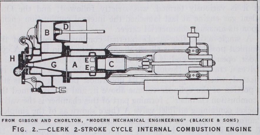
(3) Loss of fresh charge frequently occurs by "short circuit ing" through the exhaust ports, and many small two-stroke cycle engines suffer some loss of unburned gas from this cause. Clerk cycle engines have been practically superseded in small sizes by the Day engine next described, though a modern example of a small Clerk cycle design appears in the "Dolphin" petrol engine, an account of which is given in The Gas, Petrol & Oil Engine, vol. ii. But in the largest types of two-stroke gas engines the Clerk cycle prevails, with some modifications, as in the well known Koerting and Oechelhauser designs referred to later.
In each of these the crank-chamber is completely enclosed so as to be air-tight. In the two-port type the ascending piston creates a partial vacuum in the crank-chamber and the charge of fresh mixture at once enters through an automatic valve as indi cated. On the down-stroke this valve at once closes and the mixture is compressed in the crank-chamber to a few lb per sq.in. pressure ; when near the bottom of its stroke the piston first over-runs the exhaust port (on right), the expanded and burnt gases above it at once rushing out through the exhaust, and immediately afterwards over-runs an inlet port (on left) communicating with the crank-chamber, thus permitting a charge of fresh mixture to enter the cylinder. A "hump" on the piston deflects the stream of entering fresh mixture upwards and so minimizes loss by short-circuiting through the exhaust port. The piston, rising, first cuts off the inlet and exhaust ports and next compresses the entrapped charge into the combustion chamber where it is fired, and the working stroke next follows as usual. The two-port engine thus requires one valve, but the three-port engine is valveless, and is the simplest form of internal com bustion engine possible, the only moving parts being the piston, connecting-rod and crankshaft. Referring to the right-hand diagram of fig. 3, the third port is shown below the exhaust port. When the piston rises the inlet port is closed, and, as before, a partial vacuum is created in the crank chamber; when near the top of its stroke the lower edge of the piston over-runs the third port and fresh charge immediately rushes into the crank chamber. The subsequent descent of the piston first cuts off the charging port and next compresses the fresh charge in the crank chamber; the remainder of the cycle is as in the two-port type.
These two-stroke engines will obviously run equally well in whichever direction the crankshaft may be started; this property renders their reversal easy—a valuable feature in marine appli cations.
plicity, regarded as air, conforming strictly to the equation:— pv= cT (I) where p is pressure, estimated in lb./sq.f t. ; v is the volume of I lb. in c.f t. ; c is a constant, having the value of about 53.3 ; and T is "absolute temperature" in °F and is equal to the ordi nary °F plus 46o. The action is further imagined as taking place with the same mass of air always within the cylinder, and the .sii11pI CJJ1V11 allu eApall'1VL1 die I egari (ICU is atyau 11C , Z.e., no gain or loss of heat to the cylinder walls is contemplated. Fig. 4 exhibits the ideal indicator diagram of a four-stroke cycle engine with these simplifying assumptions.
Imagine the piston as at the top of its stroke with the com bustion chamber volume filled with air ; this is represented by the point 0 on the diagram, the combustion chamber volume being and the atmospheric pressure Po. The piston next per forms the suction stroke and the corresponding line of is traced on the diagram; at i the whole cylinder volume, is filled with air at atmospheric pressure (pi). The return of the piston next compresses the air into the combustion chamber, the rise of pressure with diminution of volume being represented by the (adiabatic) compression curve At the end of the com pression in-stroke the mixture is exploded and an instantaneous rise of pressure occurs from T2 to T3; next follows the working out-stroke and the exploded gases expand (again adiabatically) as indicated by 3-4. At the end of the working stroke the exhaust opens suddenly and the burnt charge rushes out, the pressure falling instantly to that of the atmosphere, as indicated by 4-1. Then during the return exhaust in-stroke of the piston the line 1 o is traced. This cycle is then repeated indefinitely.
In theory the working air is regarded as receiving a sudden accession of heat at 2 which causes its temperature (absolute) to rise from T2 to T3, and a sudden withdrawal of heat at 4, whereby its temperature is reduced from to During the periods of adiabatic compression and expansion no loss or gain of heat is considered to occur. Thus the only heat given to the working air per cycle is during the explosion 2-3, and the only heat subtracted is that during the "exhaust drop" 4-1. The difference between the heat given and the heat subtracted, or "rejected," is the (heat equivalent) of the mechanical work done by the piston per cycle. Accordingly as both heat exchanges take place at constant volume, if K„ denote the specific heat of the work ine air at constant volume we have :— ti curnmlit.ee UI the nritisn institute or l.ivii Engineers in 1905 recommended the adoption of this expression to indicate the ideal maximum thermodynamic efficiency of the four-stroke engine ; it is known as the 1905 Air Standard, and has been very extensively employed. It makes the ideal maximum efficiency increase with the compression ratio, as is shown by the following figures : For r= 4 6 8 IC) 12 14 The air std = -426 -512 .565 •602 •630 -652 In spite of the simplifying assumptions involved it has very well served its purpose; thus, after very extended experience Ricardo, The Automobile Engineer, 1928, observed, "As we raise the compression ratio of an engine we improve both the power output and the efficiency very nearly in proportion to the increase in the Air cycle efficiency." Estimation of Horse-power.—The smaller-powered quicker running classes of gas engine are usually tested for power by some form of brake dynamometer by which the "brake" or "effective" horse power is directly determined. With larger engines indicator diagrams (see fig. 4) may be taken from the working cylinder; the average height of the figure 1234, measured by the scale of pressures of the diagram, gives the mean effective pressure on the piston in lb./sq.in. during the working stroke ; this is usually denoted by p.
Now let d denote the piston diameter in inches, s its stroke in inches, and n the number of revolutions of the crankshaft per min ute. Then the piston area is .7854 square inches, and therefore the mean effective piston load during the working stroke is d2p lb. weight.
This load works through-1-25 feet; and accordingly the "indi cated work" performed per working stroke is • 7854 p Xs I2 foot-lb. In one hour 6o X? working strokes are made and, as 2 suming them all exactly alike, the total indicated work per hour is thus • 7854 X- 5. 6o X n 2 foot-lb.
But a horse-power is, by definition, a rate of working of 33,00o foot-lb. per minute, or 6o X 33,00o foot-lb. per hour; finally, therefore the indicated horsepower of a single-cylin dered single-acting four-stroke cycle internal combustion engine is expressed by : ; and this reduces by 12X 2 X 6o X 33,000 arithmetic to:— Indicated H.P. = 992 X (4) If the engine have N cylinders, the total I.H.P. is obviously N times as great as (4) .
Suppose that by test both the I.H.P. and B.H.P. of an engine have been ascertained. Then their difference, viz., I.H.P.—B.H.P. is the horse-power absorbed in engine friction and in doing any other work incidental to the performance of the cycle of the B.H.P. .
engine. Their ratio, viz., is termed the "mechanical ef I.H.P.
ficiency" of the engine and is usually denoted by thus:— The product rip, i.e., mechanical efficiency multiplied by indi cated mean effective pressure, is termed the "brake mean ef fective pressure." The mechanical equivalent of one B.Th.U. is 778 ft.-lb. of work; and accordingly the heat equivalent of one horse-power 33,00o X 60 hour is = 2,545 B.Th.U. Suppose, for example, trial of a gas engine to show that 15 cu. ft. of coal gas was consumed per I.H.P. hour, the gas having a heat value of 500 B.Th.U. per cu. ft. Then 15X 500 = 7,500 B.Th.U. of heat are expended in obtaining 2,545 B.Th.U. of indicated work; and thus the ab solute indicated thermal efficiency = X Ioo = 7,5 If the mechanical efficiency of the engine has been found to be so that rl = o•85, then the brake thermal efficiency would be 33.9X0.85=28.8%. If the ratio of compression, r, of the en gine were 6, the corresponding ideal air standard efficiency would be 51.2%. And accordingly the relative indicated thermal effi ciency = X 100 = 66.2%. Similarly the relative brake ther mal efficiency Y = - 100 = 56.25%. These figures are from 51 ? 2 actual test results from a well-designed loo B.H.P. gas engine in 1923. The small gas engine is rarely as efficient as the large one, contrary to the steam engine.