
SPECIAL TYPES OF INTERNAL COMBUSTION ENGINES The Humphrey Internal Combustion Pump.—If the water within a partially filled, vertically placed U-tube be dis placed it will perform nearly isochronous oscillations about its position of rest. H. A. Humphrey (1906-9) has ingeniously utilized the oscillatory motion of a large water-column to effect the rais ing of great volumes of water from a lower to a higher level.
A diagrammatic view of the simplest form of the Humphrey pump is given in fig. 18. ABCD is the U-tube the arm A being closed and forming the combustion vessel, while the splayed-out arm D is open and in free communication with the upper reservoir. Through the mixture inlet an explosive charge of gas and air is introduced into A and electrically fired ; the pressure developed by the explosion drives down the water level in A, correspondingly raising it in D, thus producing delivery into the upper reservoir. The great momentum of the moving water column causes the downward motion in A to continue until the pressure in the com bustion vessel becomes less than atmospheric ; the exhaust valve then opens by its own weight and at the same time the air scavenging valve is opened by the atmospheric pressure ; the burnt gases are now discharged into the atmosphere. By this time the level in A has fallen below that in the lower reservoir and a new supply of water then enters through the nest of valves EE ; during the whole of this period water is evidently being delivered into the upper reservoir. The column then comes momentarily to rest, and during the return swing to the left the rising level in A first closes the exhaust valve by its impact and next compresses above it a mixture of residual exhaust and scavenge air ; when the column is thus again brought to rest the pressure in the upper part of A being considerable, the column begins its second swing to the right and in the course of this the pressure again falls to less than that of the atmosphere but this time, by means of a suitable interlocking gear, the exhaust and air scavenging valves are held closed ; the mixture inlet valve, however, opens and an explosive charge of gas and air enters A. The second swing of the column to the left then compresses this fresh charge in A, and the cycle is then repeated. The Humphrey pump thus works on a modified four-stroke cycle (see above, "Gas Engines"), but with strokes of unequal length, the working (expansion) stroke being particularly long, which makes for its high efficiency. The cycle-frequency depends upon the mass of water in the "play" pipe, and is determined by varying the length of this pipe ; a frequency of to 3o cycles per minute is commonly employed. The pump is very quiet, as the exhaust takes place at practically atmospheric pressure, and is suitable for lifts up to 15o feet. The pump is also built to work on a two-stroke cycle; and later designs pro vide for the use of oil as fuel.

At the Metropolitan Water Board's 30o horse-power installation at Chingford, Essex, England, are four pumps each with a cylinder A seven feet in diameter, and each designed to lift 4o million gallons per diem; and a fifth, with a five-foot cylinder dealing with 20 millions per diem. These are all operated by pro ducer gas supplied by four Dowson gas producers using anthra cite as fuel. The consumption per actual pump-horse-power hour is only about 0.9 lb. of anthracite.
The Still Internal Combustion Steam Engine.—Com monly some 3o% of the total heat of the fuel used in a Diesel engine is carried away in the exhaust gases at a (full load) tem perature of some 800-900° F, and, in favourable circumstances, a saving in running costs can be effected by utilizing this heat in special types of steam boiler. W. J. Still has gone further by arranging for the exhaust and jacket heat to add directly to the power output of single-acting Diesel engines ; this he has effected by enclosing the lower portion of the working cylinder, and arranging for this end to work as an ordinary high-pressure con densing steam engine.
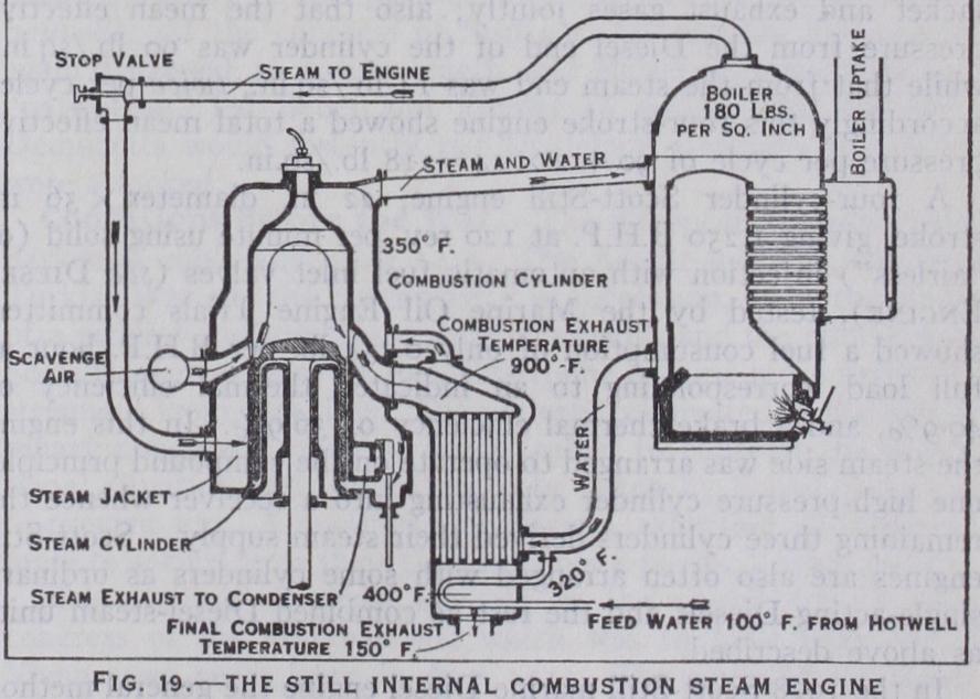
The method adopted is illustrated by fig. 19. Above the piston the usual Diesel sequence of operation is performed. The upper (Diesel) part of the cylinder is heavily water-jacketed, and the lower part is steam-jacketed; in the steam-jacket works a slide valve by which admission of steam to the lower end of the cylinder is regulated ; the exhaust steam from the cylinder passes into an ordinary condenser. The water-jacket is connected at its top with the upper part of an auxiliary oil-fired steam boiler (shown on right), and at its lower end, through a feed-heater, with the bottom of the same boiler. Through this feed-heater passes the exhaust from the Diesel end of the working cylinder, entering at a temper ature of, say, 900° F and leaving at the much reduced temperature of some 150° F only, thus giving up heat to the water system. This heated feed-water then enters the cylinder jacket, and receives some further heat by conduction through the working barrel, thereby rising in temperature to, say 35o° F. The water (and steam) circulation continues through the upper pipe to the auxil iary steam boiler, in which a pressure of 18o lb./sq.in. is shown.
From the top of the boiler dome is taken the dry working steam to the steam jacket and thence, via the slide valve, to the lower end of the working cylinder. In this way heat conducted through the upper part of the cylinder liner (or "working barrel") , to gether with much of the heat ordinarily wasted in the exhausted burnt gases is recovered and utilized, and at full load it is claimed that up to 7 lb. of steam may be obtained per B.H.P. hour of the engine, with an increase of about 20% in power output, and much improved economy in fuel consumption. The cylinder liner in the Still engine is usually only about one-third of the normal thick ness, and is ribbed externally to improve its heat-conducting properties.
Trials by C. B. Boys showed that, per B.H.P. hour, 3.28 lb. of steam was obtained from the jacket alone, and 6.o lb. from the jacket and exhaust gases jointly; also that the mean effective pressure from the Diesel end of the cylinder was 90 lb./sq.in., while that from the steam end was 14 lb./sq.in., twice per cycle; accordingly this four-stroke engine showed a total mean effective pressure per cycle of 90 + 2 X 14=118 lb./sq.in.
A four-cylinder Scott-Still engine, 22 in. diameter x 36 in. stroke, giving 1,25o B.H.P. at 120 rev. per minute using solid (or "airless") injection with automatic fuel inlet valves (see DIESEL ENGINE), tested by the Marine Oil Engine Trials committee, showed a fuel consumption of only 0.354 lb. per B.H.P. hour at full load, corresponding to an indicated thermal efficiency of and a brake thermal efficiency of 36.9%. In this engine the steam side was arranged to operate on the compound principle, one high-pressure cylinder exhausting into a receiver whence the remaining three cylinders derived their steam supply Scott-Still engines are also often arranged with some cylinders as ordinary single-acting Diesels and the rest as combined Diesel-steam units as above described.
In the 1928 Scott-Still marine Diesel engine the general method of waste-heat recovery was unchanged but the steam cylinders were separate double-acting cylinders of normal type. The 3,000 B.H.P. Scott-Still engine of 1928 design, for example, comprised six single-acting two-stroke solid injection Diesel cylinders of 27 in. bore and 45 in. stroke, working in conjunction with two double-acting steam cylinders of 25 in. bore and 45 in. stroke at a normal speed of Ios rev. per minute.
The Still engine involves the addition of a feed heater, an auxil iary boiler, a condenser, and all the associated steam engine mechanism to the ordinary Diesel engine; but it enjoys, among others, the following valuable compensating advantages :—( ) An extremely high fuel economy. (2) By firing-up the auxiliary boiler the total mean effective pressure can be substantially increased thus enabling the engine safely to carry a big overload. (3) Steam from the auxiliary boiler serves for starting the engine, and the cylinders are well heated when the Diesel parts come into opera tion; the use of compressed air for starting is thus avoided. (4) Manoeuvring is also simplified, and again the use of compressed air is rendered unnecessary.
Briefly, in the Michell bearing the rubbing surfaces are capable of tilting, thus becoming slightly inclined to one another in the direction of motion, so that the oil film between them is wedge shaped with the thicker edge at the entrance. A continuous flow of oil between the surfaces is thus induced and the film constantly renewed, thus effectively preventing actual metallic contact from occurring. In these, circumstances the coefficient of friction is reduced to about •o018, i.e., only some o of the value when the rubbing surfaces are maintained strictly parallel to each other.
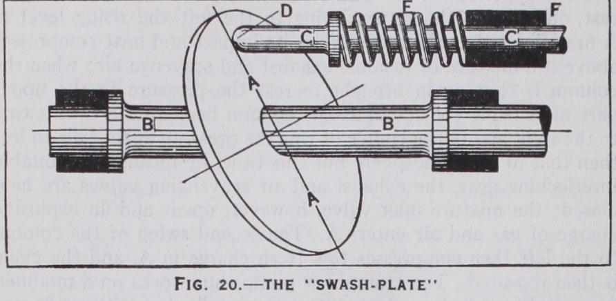
A plane disc fixed obliquely on a rotating shaft is an old mechanical device for obtaining reciprocating motion, and was illustrated and described as long ago as 1841 by Willis in his classic Principles of Mechanism wherein also it is shown that if the shaft rotates uniformly a simple harmonic motion of the reciprocating piece results. The device is illustrated in fig. 2o; AA is the "swash-plate" or "slant," mounted obliquely upon a shaft BB, and CC is a rod whose end is kept always in contact with the plate as indicated. Obviously, if the shaft BB rotates on its axis the rod CC will reciprocate. Conversely, if CC recipro cate,—and friction is not too great—it will communicate to BB an angular motion through a semicircle in making its stroke from right to left; by a second rod similar to CC, placed to the left of the swash-plate the shaft can be caused to perform a second semi circle, thus completing a revolution. This is the modes operandi of the swash-plate engine; CC becomes the piston and piston rod, the spring E the working impulse, and the bearing F the engine cylinder. Hydraulically-operated multi-cylindered swash-plate engines have been used for years in warships for training the big guns; these engines are both of single- and double-swash-plate design, the latter having two swash plates set back to back, con ferring valuable balancing qualities.

The nature and action of the Michell crankless gas engine will now be clear from inspection of the diagram fig. 21, showing a "slant" with eight cylinders, arranged in opposed pairs spaced equally around, with their axes all parallel to that of the shaft. The working pressure is communicated to the "slant" through Michell thrust slippers having spherical seats, as indicated. As the engine operates on the four-stroke cycle (see above "Gas En gines"), opposed pistons are coupled together by means of a yoke in order to effect the suction strokes.
Eight 28o horse-power National-Michell crankless engines, each direct-coupled to a Michell gas booster, were installed at the works of the Australian Gas Light Co. of Sydney, N.S.W. Each unit delivers 500,00o cu.ft. of gas per hour at a pressure of 7.25 lb./sq.in., when running at its normal speed of 75o rev. per minute. (G. A. By.)