
VIL ELECTROSTATIC INSTRUMENTS Electroscopes and Electrometers.—As their names indicate, these instruments are intended respectively for the detection and measurement of electric charges or differences of potential. troscopes were the first electrical instruments to be devised, and take their origin from William Gilbert (1544-1603 ), who first developed the knowledge of electrical phenomena from the isolated fact known to the ancient Greeks, that amber could be fied by friction. His electroscope consisted simply of a light pivoted metallic needle, either end of which was attracted on the approach of an electrified body. The next step was to utilize the repulsion of two similarly fied bodies. Benjamin Franklin, employing two linen threads hanging close together, and du Fay, Canton, Henley and Cavello double straw or pith ball scopes. Henley's electroscope (fig. 21) was a crude form of electrometer, and consisted of a pith ball suspended at the lower end of a light pivoted arm and normally just touching a metal sleeve. When the latter was charged, it imparted part of its charge to the pith ball and repelled it, and the amount of the charge was roughly indicated by an arc divided in degrees with its centre at the pivot. Cavallo's electroscope (c. 1770) was the prototype of the modern sion electroscopes, having a glass bell jar with a metal stem sealed into its neck (fig. 22). At the top of this stem was a shaped metal cap A, which served as a charging knob and also protected the glass and insulation of the stem from rain if the instrument was used in the open air ; while at the bottom of the stem two pith balls were suspended by fine silver wires. Two metal strips, B and C, were cemented on the inner surface of the bell jar and connected to earth. In 1782 Volta increased the sensitive ness of this form of electroscope by adding a condenser, and Fara day showed that for its indications to have a definite meaning the interior of the glass vessel should as far as possible be covered with metal, leaving only small spaces for the observations of the movements of pith balls. In 1787 Abraham Bennet substituted gold leaves for the pith balls, the form of electroscope shown in fig. 23, in which the stem carrying the gold leaves and charging knob is supported on a rectangular glass frame inside the bell jar which is coated on the inside by a number of strips T of tin foil, all connected to a terminal on the base, which can be connected to earth. The interior of the instrument is kept perfectly dry by means of a vessel containing cal cium chloride and sulphuric acid, and an ebonite plug slides on the upper part of the stem. This plug normally closes the jar, but when the instrument is in use, it is slightly raised, leaving a small air space between the stem and the cap of the bell jar.
Until about the commencement of the present century electro scopes were little used, except for teaching purposes in connection with electrostatics, but the discovery of radio-active materials and their power of discharging a charged body by ionization led M. and Mme. P. Curie to employ the rate of discharge of an electro scope as the best means of detecting the intensity of radio-active bodies, and a large number of new forms of electroscope have been introduced. That of M. and Mme. Curie is diagrammatically shown in fig. 24. It consists of a small brass case having a block of sulphur SS at its top, from which a metal strip B with a gold leaf L depends. The case is pro vided with two holes at its sides and a horizontal metal wire car ries a charging knob C projecting through one of these holes and a condenser plate P' at its other end. A second condenser plate P, just below the first, is connected to the case. The instrument is first charged by the knob C until the gold leaf L diverges from the strip B by a convenient amount, after which a cap is fixed over C and the leaf should maintain its position for some time if the insulation is satisfactory. On inserting a small amount of radio active material between the plates P and P', however, the ioniza tion of the air between the plates causes the charge to leak away, and the rate of fall of the leaf L, which can be observed in a microscope through a window in the case, measures the amount of radio activity of the material.
Somewhat similar forms of electroscopes for radio-active measurements were made by Elster and Geitel, and by C. T.
R. Wilson (I go I), but in 1903 a great improvement was made by the latter in his tilted electro scope (fig. 25). In this instru ment a single gold leaf L is employed which is attracted towards a plate P by connecting a battery of about 200 volts between the plate and the case of the instrument. Any charge of the gold leaf L then causes it to be attracted more or less strongly towards P, and it is found that if the whole case is tilted as shown, a position can be formed at which the instrument is extremely sensitive, and the tip of the gold leaf moves several millimetres when its poten tial is raised by one volt. The latest improvement in this type of instrument has been made by Wilson and Kaye (fig. 26), and is similar to the above except that the case is permanently tilted through about 45° and the final adjustment of sensitiveness is made by varying the distance of the plate P by turning the mi crometer head D. With 200 volts on the plate this electroscope gives a defection of three or four divisions on the scale in the observing microscope for only o•oi volt on the leaf.
The electroscope employed for radio-activity investigations, as well as the early electroscope of Henley, are in reality crude forms of electrometers, as they are actually used for approximate measurements. But the term elec trometer is generally restricted to instruments intended for accu rate measurements of potential differences, and designed to have a more or less definite law. The first instruments of this kind were on the "attracted disc" prin ciple, which seems to have origi nated in 1746 by Daniel Gralath of Danzig, and to have been termed by him an "electrometer" ; but the earliest practical forms were those of A. Volta and Sir Wm. Snow-Harris, in which a flat horizontal disc was suspended from the arm of a balance just over a similar fixed insulated plate.
When the latter was electrified it attracted the suspended plate downwards, and balance could be restored by adding weights on a scale pan at the opposite end of the balance arm. Fig. 27 shows one form of Snow-Harris electro meter in which C is the suspend ed disc above the insulated disc which is shown connected to the knob of a Leyden jar, while the outer coating of the jar is con nected to the frame of the elec trometer and thus to the sus pended plate, so that the P.D. between the plates is the same as that between the coatings of the jar. Snow-Harris found that the weight required to restore balance was proportional to the square of the charge or the P.D. of the jar.
In 1857 Lord Kelvin turned his great mathematical and in ventive skill to the subject of electrometers, and produced two forms which have persisted with only detailed improvements to the present day. The first form was derived from the attracted disc electrometer, but had the very important addition of a "guard ring," which made its in dications of absolute value. In the simple attracted disc elec trometer the electrostatic field between the two plates is not uni form, as the lines of force curve round from the edges of the two discs. But if the fixed disc is made much larger than the sus pended one, and the latter is sur rounded by a plate which nearly touches it all round, then if the movable plate is exactly in the same plane as the surrounding plate when the measurement is made, the electrostatic field be tween the suspended and fixed plates will be practically uniform, and it can be proved theoretically that the force in dynes be tween them ± will be given by the expression f = A Vt 2 where V is the P.D. between the plates in electrostatic units of volts, A the area of the suspended plate in square centimetres, and d the distance between the suspended and fixed plates in centimetres, so that V = d 8 A • d and A are known, there fore, the P.D., V can be determined directly from the force re quired to balance the attraction.
Lord Kelvin employed this principle in two forms of electrom eter, one of them being known as his portable electrometer, fig. 28, the essential parts of which are shown diagrammatically in fig. 29. H.H. is a plain disc of metal fixed inside the bottom of a glass jar, which is coated inside and outside with tinfoil to form a small Leyden jar. In the middle of this disc H.H. a square hole F is cut, and a slightly smaller square plate of aluminium foil provided with an arm at one side is mounted on a horizontal stretched wire so that it will just swing through the hole F like a trap door. The wire is given an initial twist so that the alumi nium plate normally rests a little below the upper surface of the disc H.H., and the arm which is provided with a crutch and cross wire is therefore tilted upwards. A circular plate G is fixed on the end of a micrometer screw above the disc H and is connected through the metal cover to the outer coating of the jar. When there is a difference of potential between the two coatings of the jar, and therefore between the two plates, the aluminium plate is attracted upwards and by varying the distance between the plates by the micrometer screw it may be made to come into exact regis ter with the plane of the disc H.H. when the indicating arm will be at zero. As the force required to attract the disc to this position is always the same, the P.D. re quired to obtain balance is simply proportional to the distance d between the plates which is indi cated by the reading on the head of the micrometer screw. The ab solute electrometer (fig. 3o) is similar in principle but, the guard plate B and aluminium trap door H are near the top of the glass case and the attracting plate A is mounted just below them on the micrometer screw. The trap door is suspended on springs so as normally to be a little above the lower surface of the guard plate, and the force necessary to bring it into exact register can be ini tially found by placing weights on the disc and observing the posi tion of the latter through the lens L. When this force is known, any P.D. can be measured by con necting it to the two plates and turning the micrometer screw till the aluminium plate is brought to register, the formula being V = d where W is the A weight initially required to produce register and g is the attraction of gravity.
The second type of electrometer was developed from the sym metrical electrometer initially devised by T. G. Behrens in i8o6 and modified by J. G. von Bohnenberger. In this type a single gold leaf is suspended midway between two vertical metal plates between which a dry pile is connected. If then the leaf is charged it will move towards the plate of opposite polarity. Fechner and Hankel made further improvements ; the latter substituting a bat tery for the dry pile, and adding adjustments to the plates and a scale for measuring the movements of the leaf. Lord Kelvin greatly improved this type of instrument in his quadrant electrom eter, the essential features of which are shown in fig. 31. A flat circular metal box is cut into four equal sections or quadrants A, B, C, D, and each section is supported on an insulating pillar and provided with a terminal, the opposite quadrant A and D and B and C being connected together by wires. A light flat paddle shaped aluminium vane U, shown by the dotted lines, is suspended by a bifilar cocoon silk suspension exactly in the centre of the quadrants and normally symmetrically between them as shown. From the centre of this needle hangs a fine platinum wire, which dips into sulphuric acid in the bottom of the glass containing vessel. This acid is conducting and it also serves the quadruple function of forming the inner coating of a Leyden jar, or keep ing the interior of the apparatus dry, of establishing contact with the vane or needle, and of damp ing the movements of the latter.
The outer surface of the glass container is partially coated with strips of tinfoil to form the outer coating of the jar. If this jar is charged, the needle can be maintained at a constant high potential by means of a small electrical machine or "replenisher" and a gauge, and if a small P.D. is then applied between the two pairs of quadrants the needle will turn so that a smaller portion of it is between the quadrants of similar potential and a larger portion be tween those of opposite potential to that of the needle, and its de flection can be observed by attaching a light concave mirror to the stem of the needle, and employing a lamp and scale as in reflecting galvanometers (q.v.). If V is the potential of the needle and and V2 the potentials of the two pairs of quadrants respectively, theory indicates that the deflection D= {V — 2 } where k is a constant of the instrument. Unfortunately, Hopkinson, in 1885, and Ayrton Perry and Sumpner the following year, noticed that this law did not hold in the Kelvin electrometer, as instead of the deflection for a given P.D. across the quadrants rising proportionally with increase of potential of the needle, it increased up to a certain potential, after which there was little further increase, and in some cases a diminution. The latter investigators traced this action to openings in a guard tube which was employed to screen the platinum wire from external electrical disturbances, and devised an electrometer in which magnetic control was sub stituted for the bifilar silk sus pension, and the quadrants were more exposed and more easily adjustable, thus enabling the the oretical law to be fulfilled, and with increase of sensitiveness.
This improvement was of great importance, as it enabled the electrometer to be used as an ac curate wattmeter (q.v.) for use in alternating current circuits, and this application was independ ently suggested in 188 i by Professors Ayrton and G. F. Fitzgerald and by M. A. Patier.
The invention of the quartz fibre by Prof. C. V. Boys has enabled quadrant electrometers to be made of much greater sensitiveness, owing to its extremely small and constant control. Among them that of Dr. F. Dolezalek (fig. 33) has been very suc cessful, because of its high sensitiveness and low electrostatic capacity. The needle and quadrants are made of very small size ; the latter being supported on short pillars of amber which give very high insulation, while the needle is of paper thinly coated with silver foil so as to have very small inertia and almost critical damping with the very small control of the quartz fibre. The latter is rendered sufficiently conducting to charge the needle by dipping it in the first place into a solution of some hygroscopic salt, such as calcium chloride, so that its surface is always moist, or better by gilding it. The whole system is enclosed, like a galvanometer, in a brass case, which shields it from draughts and external elec trostatic fields and the deflections are obtained by a small con cave mirror on the needle, through a window in the case. A torsion head on the top of the suspension can be employed to adjust the zero of the instrument. With a quartz fibre suspension 6o mm. long and 0•009 mm. diameter and a potential of i i o volts on the needle, its periodic time was 18 sec. and a deflection of 130 mm. on a scale at 2 metres distance was obtained with a P.D. of 0.1 volt between the quadrants. Even greater sensitiveness has recently been secured with this type of instrument by the Cambridge Instru ment Co. The latest improvement in the quadrant electrometer has been made by Prof. A. Compton, who has found that by slightly inclining the plane of the needle and giving a vertical adjustment to one of the quadrants, the control can be varied down to zero or even to a negative value. An instrument of this type with a gilded quartz suspension of 0•002 to 0.005 mm. diame ter has given from 15 to 140 mm. deflection at a metre with 50 volts on the needle and only o•oi volt between the quadrants, but the time to reach a steady deflection at the higher sensitivity is about 90 sec.

On the other hand the requirements of radio-activity research has caused the "string electrometer," based on the original instru ments of Behrens and von Bonenberger, to be developed into instruments of high sensitivity, low capacity and rapid response by the aid of gilded quartz fibres. In a form of string electrom eter made by the Cambridge Instrument company, a single quartz fibre of 0•002 or 0.003 mm. diameter suspended symmetri cally between two plates with 25 volts between them, will give a deflection of .044 mm. or about 5.5 scale divisions on a microscope for z volt on the needle with a critically damped period of under I second. Prof. Lindenmann has produced a deflectional "quad rant" electrometer having a 0.004 vertical gilded quartz fibre under slight tension, and two gilded glass fibres 2 cm. long and 0.02 mm. diameter cemented transversely and symmetrically upon it to serve as a needle. The ends of this needle move between four fixed plates serving as quadrants and the whole system is en closed in a small sealed metal box with windows above and below, so that it can be placed on the stage of an ordinary microscope. Prof. Lindemann's deflectional "quadrant" electrometer is an instrument which gives .4 mm. deflection or 136 divisions on the microscope for 0.35 volts between the quadrant plates and r volt on the needle.
When the electrometer principle was first applied to volt meters, P.D.'s of only r oo or 200 volts were in use, and high sensitivity was consequently essential. The first practical electro static voltmeter was the "multicellular" form devised by Lord Kelvin in 1867 (fig. 34) and was equivalent to a number of quad rant electrometers arranged vertically above one another, their vanes or "needles" being mounted on a common stem so as to add their torques. Two sets of quadrant plates only were employed in each set, and were opposite one another and connected to gether to one pole of the circuit, the vanes being suspended by a fine wire and connected to the other pole. When the system was at zero, the vane system hung so that it was just about to enter between the fixed quadrants at two opposite edges. When a P.D. was applied between the vanes and quadrants the former were drawn further and further in against the torsion of the sus pension as the P.D. was increased, and the P.D. could be indi cated by a pointer attached to the vertical spindle on a scale as shown. This instrument was very similar to the variable vane condensers now so largely used for broadcasting sets and, in fact, its operation, like that of all electrometers, depends on this variable capacity. The energy stored in a condenser of capacity C and with a P.D. V between its plates is E= so that the force between them F = aE =-1V2 a C , where x is the distance ax ax between them; or the torque T = aE _ 2 V2 ac where 0 is the ae ae angle of rotation of the vanes. In the multicellular voltmeter, as in the vane condenser, the capacity is nearly proportional to the area over which the moving and fixed vanes overlap, i.e., to the angle 0, so that a . is nearly constant. Thus, the torque, and ae consequently the deflection 0, is approximately proportional to the square of the P.D. until the moving vanes are drawn nearly completely in, after which the increase of the deflection dimin ishes. Such voltmeters therefore only commence to have a useful reading at a moderately high fraction of their maximum voltage, but then have a widening scale, closing up again as the maximum is approached. This is a very suitable scale for supply circuits, though less suitable for general measurement.
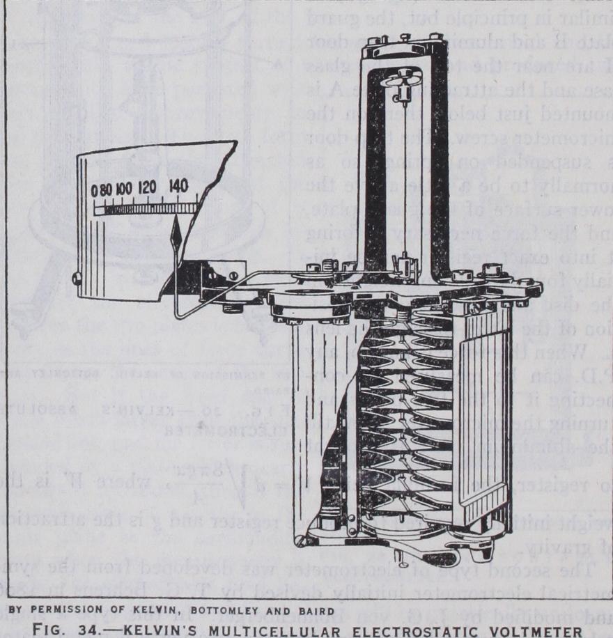
The multicellular voltmeter came into fairly considerable use for circuits up to a few hundred volts, but was very slow in indi cation owing to the large inertia of its vane system. It was damped by a disc at the bottom of the spindle which turned in a vessel of oil.
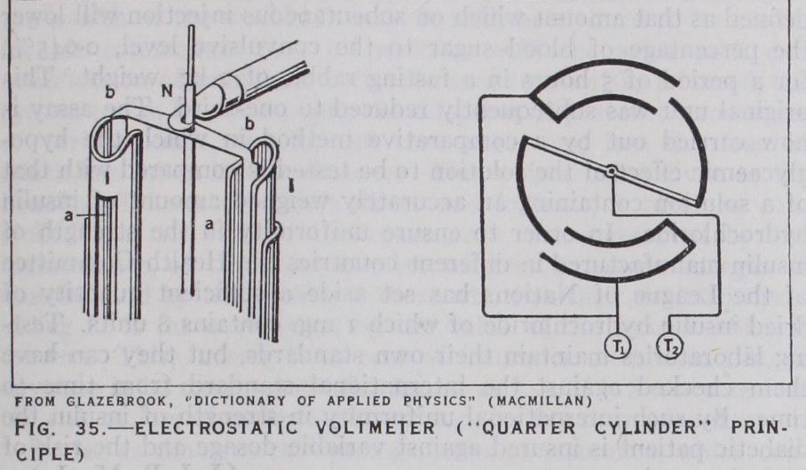
For higher voltages Lord Kelvin introduced another form hav ing only two fixed vanes in a vertical plane, with a single vane moving system having a pivoted horizontal axis. Ayrton and Mather devised electrostatic voltmeters for both low and high P.D.'s on what they termed the "quarter cylinder" principle. It may perhaps best be described as a quadrant electrometer in which the moving vanes are bent over so as to form portions of cylinders parallel to the axis, and the quadrants are then also portions of cylinders which are arranged concentrically. This construction has the advantage of reducing the moment of inertia and increasing the rigidity of the system for a given capacity, and therefore of increasing the rapidity of reading. Suspended instruments of this type have been made for P.D.'s down to 8o volts and pivoted horizontal axis switchboard instruments for 3,00o volts or more. These latter instruments are damped by piston air dampers, but Carpentier has adopted the same form, but mounted between the poles of a powerful horseshoe permanent magnet which produces the damping by the eddy currents induced in the moving system. Extra high voltage voltmeters have been made by the Westing house company and others on the same lines, but with the system immersed in oil which gives a greater dielectric strength against arcing, a greater torque owing to the increase of capacity, and damping by the viscosity of the oil. Compressed nitrogen has also been employed in electrostatic voltmeters for reducing lia bility to spark, and the formation of ozone. For very high volt ages up to hundreds of thousands of volts, the instruments would become very cumbrous owing to the large distances required to avoid flashing over, but the range of the above instruments may be almost indefinitely extended for A.C. measurement by con necting a condenser in series with the voltmeter as originally pro posed by Ayrton and Perry. If the capacity of this condenser is equal to that of the voltmeter, twice the P.D. will be required for the same deflection, or if it is one-ninth of the voltmeter capacity the required P.D. will be multiplied tenfold, and so on, so that an instrument normally reading to 5,00o volts can have its range extended to 50,00o volts or more. This is generally effected by connecting one terminal of the voltmeter to a plate or sphere on an insulating pillar with another plate at an adjustable distance near to it. On the other hand the Snow-Harris attracted disc electrometer (q.v.) has been adapted as a high voltage voltmeter by Lord Kelvin in his Volt balance, and by Jona, Siemens and Halske, Grau and others.
BIBLIOGRAPIIY.-Electrical Measurements: Laws, Electrical MeasureBibliograpiiy.-Electrical Measurements: Laws, Electrical Measure- ments; Dictionary of Applied Physics, vol. ii.; Gray, Absolute Meas urements in Electricity and Electrical Magnetism; Fleming, Handbook for the Electrical Laboratory ; Kempe, Handbook of Electrical Test ing; Papp, Electrical Engineering Testing; Hague, A.C. Bridge Methods; Northrup, Methods of Measuring Electrical Resistance; B.A. Reports on Electrical Standards; Rayleigh, Electrical Measurements; Jaeger, Electrische Mess-Technik ; Orlich, Kapazitat and Induktivitat; Armag nat, Mesures Electriques; Lippmann, Unites Electriques Absolues; Bruckman, Magnetische en Electrische Metingen.
Indicating Instruments: Drysdale and Jolley, Electrical Measuring Instruments; Laws (as above) ; Edgcumbe, Industrial Electrical Meas uring Instruments; Murdoch and Oschwald, Electrical Instruments; Bolton, Electrical Measuring Instruments; Jansky, Electrical Meters.
Supply Meters: Gerhardi, Electricity Meters; Solomon, Electrical Meters; Laws (as above) ; Jansky (as above) ; Murdoch and Osch wald (as above) ; Konigswerthe, Elektricitszahler.
Laboratory Instruments: Laws (as above) ; Fleming (as above) ; Hague (as above) ; Irwin, Oscillographs. (C. V. D.)