
BRAKE. A means of controlling the speed of a movement, or of totally arresting it. Nearly all brakes act frictionally, though the opposition of a piston in a cylinder can be applied for retard ing purposes, converting the cylinder into an air-compressor for the while. Dynamic braking is another non-frictional method.
an electric motor being caused to run as a generator, so checking the speed of a vehicle or a machine, or causing a total stop. Most friction brakes act on revolving elements, as wheels or drums, but slipper brakes pressing on flat surfaces are applied as for tramcars, mechanically or magnetically operated, and a pincer or forcep type grips each flank of a rack in some of the mountain railways. A rope also serves for the application of a brake device in a few cases.

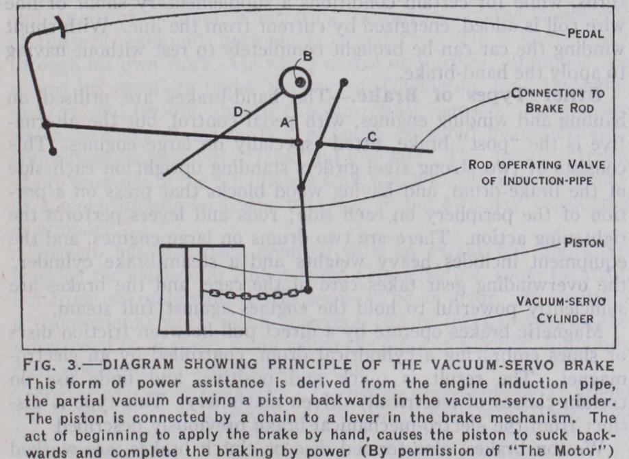
In the Westinghouse vacuum-servo system a brake cylinder has one end open to atmosphere, the other end communicating with the engine induction-pipe through a control valve which regulates the resultant pressure on the piston. The brake levers are so devised that application of the brake pedal first brings the brake shoes into contact with the drums; then further foot pressure affects the control valve and opens the communication between induction-pipe and brake cylinder, thus causing the pressure of the atmosphere to move the piston and tighten the brakes still more. The braking force is directly dependent on the foot pressure.
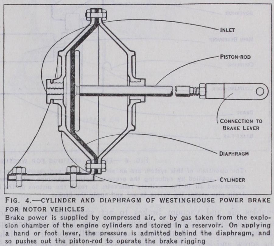
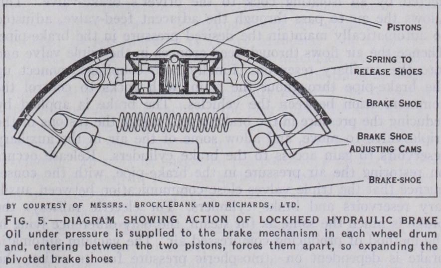
The Westinghouse power-brake acts by air from a small com pressor or by gas from the explosion chamber of a petrol engine. The control may be exercised either by foot-valve or hand-valve, and the brake-cylinder for each wheel is in the form of a pair of covers, one with foot to bolt to the chassis. The cylinder diame ters range from yin. to rein. according to weight of vehicle. Instead of a sliding piston, there is a flexible diaphragm (see fig. 4) that moves as the pressure comes through the pipe joined up at the back cover, and pushes the rod outwards. The latter connects to a reversing crank, and so to the brake-rod. There is a slotted link fitment to the existing hand-brake to make this independent of the power-brake. Hydraulic power has the ad vantages of simple flexible pipe connections to the wheels, and a perfectly compensated action, since the pressure is equal in all directions. The Lockheed system, which is fitted to numerous makes of cars, has a small pump or master cylinder attached to the flywheel housing, forcing oil along pipes and through rein forced rubber connections to a cylinder in each brake assembly. Two small pistons in each cylinder expand the brake shoes, as evident from fig. 5 (from a Brocklebank car). The shoes are pivoted at the opposite side of the circle, in the usual manner. The pistons are r 4in. in diameter, and the normal pressure is about r oolb. per sq. in., rising to 3 5olb. in emergency. The fluid used is a mixture of equal parts of castor-oil and ether, and certain stabilising ingredients added.
The Westinghouse automatic brake operates by compressed air furnished by a compressor on the engine, and stored in its main reservoir. The essential parts include those indicated in the diagram (fig. 6), commencing at the steam stop-valve, supplying steam through the air-compressor governor. The last-named shuts off steam when the required air pressure is reached. The com pressor passes air into the main reservoir, which is directly con nected by an isolating cock to the driver's brake-valve. This allows the air to pass through the adjacent feed-valve, adjusted to automatically maintain the desired pressure in the brake-pipe. Thence the air flows through feed grooves in the triple valve and into the auxiliary reservoir. Finally hose couplings connect up the brake-pipe throughout the train, with cocks to control the communication between the vehicles. The brake is applied by reducing the pressure in the brake-pipe, causing the pistons of the triple valve to move, and allow some of the air in the auxiliary reservoirs to gain access to the brake cylinders. Release occurs on restoring the air pressure in the brake-pipe, with the conse quence that the triple valves close communication between auxil iary reservoirs and brake cylinders. For electric railways the brake is much the same as for steam, the only difference lying in the method of producing compressed air. The vacuum automatic brake is dependent on atmospheric pressure for its action, the brakes being normally kept off by the state of vacuum existing in the train-pipe and cylinders. An ejector on the engine produces the vacuum and maintains it constantly. As there is vacuum both above and below the pistons in the brake-cylinders, the pistons fall by gravity and the shoes remain off. But when atmospheric air is admitted to the train-pipe, by the driver or guard, or through a break-away, it closes a ball-valve in the piston so as to seal the upper side of the cylinder, and exerts pressure on the lower side of the piston, forcing it upwards and actuating the brake rods. The two conditions appear in fig. 7, the first view showing the state with brakes off, the second with the air represented by dots. The object of the "rolling ring" of rubber is to make a perfect joint or packing without friction, and the release-valve serves to enable the brake to be released by hand.
Magnetic brakes operate by a direct pull between friction discs or shoes embracing a cylindrical drum, controlled by an electro magnet. The result is quick and positive, and finds use on certain classes of electrically-driven machinery. This type is dis tinct from the electromechanical brake previously described.
Weston brakes, also termed disc or clutch brakes, are worked either magnetically, or by end pressure obtained from a screw or hand or pedal gear. The brake contains a number of friction discs, all brought into contact simultaneously, and giving a high gripping power which increases directly as the number of discs employed. This kind is much used on cranes. A "load" brake is one fitted to the heavier cranes, the movement of the load causing a sufficient freedom between the discs when lowering is being performed, but if the driving motor is stopped the friction reasserts itself and lowering ceases, the driver thus having perfect control.
Running-in brakes afford a means of imposing a load on an engine for a period, in order to bed down the bearings and piston rings, in imitation of the actual service of the engine, but at a reduced speed. (For brakes used as dynamometers, see DYNA MOMETER.) (F. H.) Brake Shoes for Wheel-Truing.—In making brake shoes for use on mining locomotive wheels pieces of "feralun" or artificial corundum (q.v.) are set in the mould, creating a shoe that will prevent the formation of false flanges on the wheel by constantly and uniformly grinding the wheels to the proper profile. The abrasive pieces must be set carefully to secure the desired result. With shoes of this type, braking efficiency is unimpaired and no time is wasted in keeping the locomotive in the repair shop for the purpose of wheel-truing.