BRIDGE DESIGN Loads and Forces.—In designing a bridge the following loads and forces have to be taken into account :—dead load, live load, impact, deformation stresses, wind pressure, centrifugal effect, longitudinal forces, temperature effect and erection stresses. The most important of these, in the case of bridges of moderate span, are the dead and live loads and impact.

If the load W is spread uni formly over the span (fig. 19), the bending moment may be rep resented graphically by a para bola and, mathematically, by the reaction at A multiplied by the distance to any point selected, less the intervening loads, multi plied by their distance from the point' selected, i.e., If w represents the weight per unit of length, then lV = and if x be the distance AC, then the foregoing may be written:— The shear may be represented by two triangles meeting at the middle of the span, where its intensity is zero, and, mathemati cally, as equal to the reaction at either end, less the portion of the load between the point selected and the reaction, i.e., shear at The maximum bending moment occurs at the centre where and its value is, therefore or WL while the maximum shear 8 is at the ends, and has the value wL 2 or Straining Actions in a Cantilever.—In the case of a can tilever (fig. 2o), with a load W at the extreme end, the bending moment may be represented by a triangle whose maximum depth is at the support, where obviously the intensity is WL, and the value at any other point is W multiplied by the distance from W to the point. The shear can be represented by a parallelogram whose depth is equal to W. If W be spread uniformly over the span (fig. 21), then the bending moment diagram becomes a parabola, the intensity at the support being WL or wL2 if the load per unit of length is w. The 2 2 value at any other point is the product of the loads to the right of the point multiplied by half the distance between the point selected and the end of the canti lever. The shear gradually in creases from zero, at the end, to a maximum of W, at the support, and so can be represented by a triangle whose depth at the sup port is equal to W or wL.
Calculation of Stresses in a Girder.—The bending moment caused by a load, or system of loads, is resisted by the amount of material in the beam, but this resistance varies, not only with the amount and strength of the material, but with its shape or disposition. The moment of resistance is the summation of the products obtained by multiplying the strength of each small component of the cross section by the distance of its centre of gravity from the central or neutral axis. In the case of a rectangular cross section (fig. 22) width b, depth d, the moment of 3 resistance equals f bd , where f is the strength of the material for I2 unit sectional area. If b were reduced to b while d was increased 2 to 2d, the area of the cross section would be the same, but the 3 moment of resistance would have increased fourfold to f d It is evident from this that the greater the 3 depth, or the more the material can be kept away from the neutral axis, the stronger the beam for a given amount of material.
This is effected in practice by the use of a thin web with flanges top and bottom (fig.
23). The web is of so little value in com parison with the flanges that it is usually neglected in considering the moment of resistance which is then arrived at by multiplying the area of one flange by the vertical distance between their centre of gravity. If a=area of one flange, d=distance between centres of gravity, and f be the safe working stress of the material, the moment of resistance=fad. This can be equated to the bending moment, as they must be equal for safety, so that BM=moment of resist ance= f ad. To ascertain the sectional area of the flanges, all that is therefore necessary is to divide the bending moment by the depth of the girder, multiplied by the safe working stress :— a= df B The most economical depth varies from about one- tenth to one-fifteenth of the span, When the span exceeds about soft., a solid web usually becomes uneconomical, and it can be replaced by a system of vertical posts and inclined ties or struts. These members can be arranged in various ways, each type having its own name, such as Pratt, Warren, Linville, etc.
The stress in each member of such a lattice girder can be ob tained either graphically by means of a stress diagram, or analyti cally. The graphical method is as follows :—make an outline dia gram of the girder, or truss, as it is often called (fig. 24), using a definite scale, and letter each compartment according to Bow's notation. Set out the loads below each other using any conveni ent scale (fig. 25). Calculate the end reactions and mark them off on the scale of loads. Fig. 25 shows a Pratt truss so treated. The truss is in equilibrium and consists of a series of triangles, and, by a proposition in statics, the forces acting on these tri angles can be represented by a closed polygon, each side of which is parallel to one force and represents the force in magnitude and direction. From point P, draw PA parallel to member PA on the truss. From 0 draw OA parallel to member OA. These two lines intersect at A, and the sides of the triangle OPA represent the forces (to scale) acting in members P0, OA and AP in magnitude and direction. The character of the force, whether compression or tension, can also be ascertained by noting the sequence of the reading of the forces. Taking the sequence at point P, PA reads away from P; put an arrow on the truss diagram indicating that direction. OA reads towards P; indicate this with an arrow. Re peat this later at each point and it will be found that arrows > < indicate tension in the member and arrows < > indicate compression. Having solved tri angle OPA, draw from point A a line AB parallel to member AB, and from Q a line QB parallel to member QB. These lines AB and QB intersect at B, and the sides of the polygon PABQ represent the forces acting in members PA, AB, BQ and load QP in mag nitude and direction. Proceed thus until all the members of the truss have been dealt with.

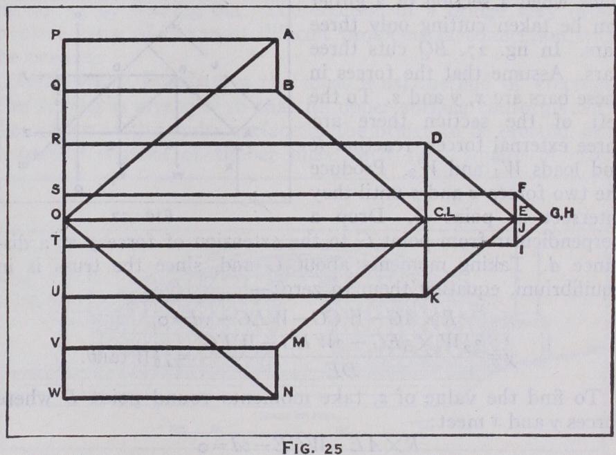
Analytically, the stresses may be found as follows. Assume for simplicity uniform loadings at each equal panel point (fig. 26), then: R=3W+ T =32W. The shearing or vertical forces must 2 obviously be taken by the vertical posts in the truss. Stress in FG = R— (W+W+W) =31W-3W= W 2 stress stress in BC = W, as it is merely a hanger transmitting load W to the point B.
The stress in the diagonals is due to their transmitting the vertical shearing forces in a diagonal direction from the bottom to the top boom; their values will, therefore, be the vertical shear multiplied by length of diagonal X sece, if 0 be the length of vertical post angle of the diagonal members to the vertical.
The stress in top flange DF = stress in in DGX sin° = 6 Wtane+ i 2 Wtan = 72 Wtan°. The stress in top flange FH = stress in in sine = 7 2 J4 tane+ Z Wtan° = 8 W tan°.
The stresses may also be obtained by Ritter's method of sec tions when a section of a girder can be taken cutting only three bars. In fig. 27, BQ cuts three bars. Assume that the forces in these bars are x, y and z. To the left of the section there are three external forces, reaction R and loads and Produce the two forces x and z until they intersect at point G. Drop a perpendicular from point G to the extension of force y at a dis tance d. Taking moments about G and, since the truss is in equilibrium, equating them to zero:— Generally, if S is the stress in any bar and L the perpendicular distance from the join of the other two bars cut by the section, and M is the moment of the forces on one side of that join, then SL = M.
Influence Lines are curves showing, for one component part of a beam or truss, the shearing force, bending moment, stress, deflection or similar function for all positions of a moving load.
Referring again to the simple beam, the bending moment dia gram for a load W at C indicates that the amount of bending at D is represented by the ordinate dd' (fig. 28). Similarly, if the load is moved to E, the corresponding bending moment diagram indi cates the amount of bending at D to be dd". For a number of positions of the load, the amount of bending at D may be plotted as ordinates on a graph whose abscissae are the corresponding positions of the load. The resulting curve will be the influence line for the case in question and as indicated on the figure. This particular influence line further indicates that for all positions of the load there is induced a ing moment of the same type; and for a uniform load, the maximum bending moment at D would be attained by loading the whole span. More generally, where a moving load may induce either a positive or negative effect on a member, the influence line gives a ready means of showing where load should be applied in order that the maximum possible effect may be attained.
Calculation of Stresses in a Continuous Girder.—When girders are carried continuously over more than two supports, or where the girders, instead of merely resting, are more or less rigidly built into the supports, the reactions of the supports can not be established by the usual elementary methods. This is due to the fact that the continuity, or building-in fixity, alters the simple distribution of the reac tions. The theorem of three mo ments supplies an equation en abling the bending moments over the supports to be calculated, and hence the reactions may be determined. Fig. 29 indicates the spans of a continuous girder.
The general equation for these two spans is:— Mp, are the bending moments at P, Q and R respec tively. are the areas of the bending moment diagrams on spans 1p and respectively, due to the loads on these spans, the spans for this purpose being considered as separate independent spans. is the distance of the centre of gravity of from sup port P. x,- is the distance of the centre of gravity of from support R. E= modulus of elasticity of material of girder. I= moment of inertia of girder. Sp, Sr are the distances which sup port Q, falls or rises below or above supports P and R respectively.
This equation is applied to consecutive pairs of spans from end to end of the girder, and thus furnishes the necessary equations to solve the bending moments over the supports. Of necessity the section and modulus of elasticity of the girder and the relative deflection of the supports must be known beforehand. Accord ingly, the design of continuous girders usually necessitates the adoption of trial and error methods before suitable sections can be chosen. Usually, the moment of. inertia is assumed to be constant throughout the girder, otherwise the general equation requires considerable modification in detail.
Calculation of Stresses in a Metal Arch.—The stresses in a metal arch are the same as those in the curved top member of a braced girder in which the tom tie has been replaced by yielding abutments, and the web system has been omitted (fig. 3o). If the arch is loaded formly, the stress at the crown, or the horizontal thrust at the springing, is H = W where L is the span and R is the height or 8R rise. The thrust in the arch at any other point is proportional to the secant of the angle a that a tangent line to the curve at that point makes with the horizontal, and its value is Hseca.
These values would be absolutely correct in the case of an arch of parabolic outline uniformly loaded, as its centre line would then conform to the outline of the bending moment diagram, and the thrusts would all be absolutely central. In actual practice an arch, even if parabolic in shape, is not subjected to a uniform dead load, on account of the varying dimensions and weight of the spandril filling necessary to secure a horizontal platform, and the arch itself is not rigid but elastic, and changes shape under the moving loads. The foregoing values for the thrust can, there fore, only be looked upon as approximate and the stresses are, in reality, indeterminate, except in the case of the three-pinned arch where pins or hinges have been inserted both at the springings and crown. Many different mathematical studies have been made, based upon assumptions as to the elastic properties of metal arches, or upon the theorem of least work. They yield approxi mate solutions that, by repeated trial and error, give results within a close margin of each other, and permit the safe design and con struction of arches of very large span, the most impressive example of which is the Sydney bridge completed in 1932, with a span of 1,65o feet.
Calculations of Stresses in a Masonry Arch.—As in the case of the steel arch, the masonry arch may be considered as the top chord of a bow-string girder, taking compression and also sheer stress, the thrust from the skewbacks taking the place of the bottom chord tension member. For any loading, the bending mo ment diagram, as drawn for the equivalent beam span, gives the ideal shape that can be adopted for the arch. Since, however, the loading on a bridge varies, the best design for the arch is that which will most nearly follow the lines of thrust for all cases, and at the same time give as small bending action as possible. Many shapes have been adopted for arches, e.g., semi-circular, seg mental, elliptical basket-handle, gothic.
The most generally used materials are brick, stone and concrete. None of these materials is adapted to withstand tensile stress. The normal rule which automatically provides a factor of safety is that the thrust should be confined to the middle third of the rib section. This implies absence of tension, together with the fact that the maximum stress never exceeds twice the average. A further implication is that the average stress is usually low and, consequently, the dead weight of the arch increases rapidly with the span, thus severely limiting this type of construction for large spans. The great majority of masonry arches are hingeless partly due to the fact that until recently the theory of the arch has not been fully understood. The accurate determination of stress where there are no hinges is extremely difficult, owing to the nature of the materials. For instance, when mortar joints set, the consequent general settlement, though minute, may entirely alter the stress distribution. The introduction of reinforced con crete into arch construction, with the consequent permission of tensile stress, has opened the field considerably for larger spans. The largest reinforced arch which has been constructed, namely the Pont Adolphe, Luxembourg, has a span of s 78f t., while the bridge at Berwick, commenced in 1925, includes a reinforced con crete span of 361f t. 6 inches.
Manufacture.—In the case of masonry bridges, complete detail drawings are prepared of every stone to be dressed, and these are sent to the quarries from which the material is to be obtained. Each stone is cut exactly to size and numbered so that when sent to the site it fits accurately into place, allowance having been made for the joints and beds which are usually +in. thick. For metal bridges, detailed drawings are made of each member, and lists of all the different materials required sent to the rolling mills in the case of mild steel, or to the foundry in the case of cast iron or other castings. While this material is being prepared, the work is drawn out full size on the floor of a building termed the template loft. Here templates of thin wood or sheet iron are cut to the right shape, and holes are drilled through them where every rivet or bolt is to go. When the material arrives at the bridge yard the templates are laid upon it, every hole marked out with steel punches, and the required shape and length outlined.
After that, it is passed to the sawing, shaping, planing and drilling benches. It is then assembled into units and riveted up. The units or members are assembled together temporarily to form complete girders to make certain that they fit each other properly, and after being painted with identification marks, they are dismantled and forwarded to the site.
Piers and Abutments.—The supports upon which a bridge rests are termed abutments in the case of those at the ends, and piers in the case of those occupying intermediate positions. They may take the form of timber or concrete piles driven hard into the ground, or screw piles of cast iron may be used in soft soils. All these are suitable for light structures, but the most usual form of support consists of a mass of concrete or masonry carried down to firm ground. The necessary excavation is done inside a timber or steel cofferdam, or box, to exclude any water that may be present and to hold up the ground, the sides of the cofferdam being formed by rows of piles which are either drawn or cut off at a convenient level at the conclusion of the work.
Another common form of support is obtained by sinking cylin drical or rectangular caissons, and loading them with temporary weights or with the masonry of the pier or abutment itself. The ground inside the area of the caisson is excavated by digging, com pressed air being employed if necessary to keep the water out. The weighted caisson keeps following the excavation down, and, when a satisfactory stratum is reached, the whole or remainder of the caisson is filled with concrete. If any doubt exists as to whether the foundations are satisfactory, they are test-loaded by means of weights, temporarily placed upon them, equal to the full load that they may ever have to carry, and the subsidence is noted. In normal circumstances, the cost of the substructure and the cost of the superstructure should be approximately equal, and this serves as a useful check on the efficiency of the design.
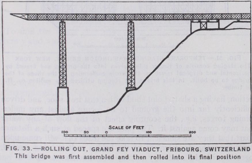
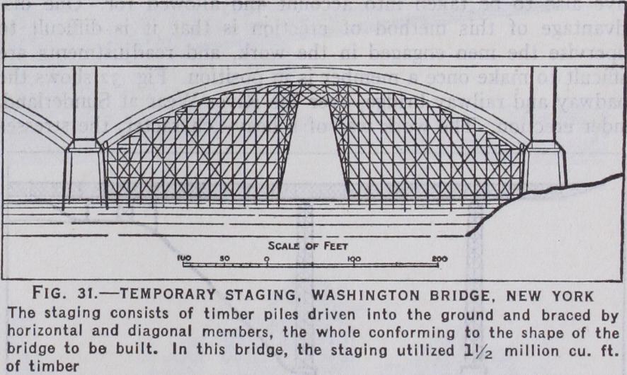
Generally speaking, there are four ways of erecting a bridge, viz., by means of temporary staging, by cantilevering out, by roll ing out or by floating out. The erection of a bridge very often involves some of the most difficult problems in connection with the project.
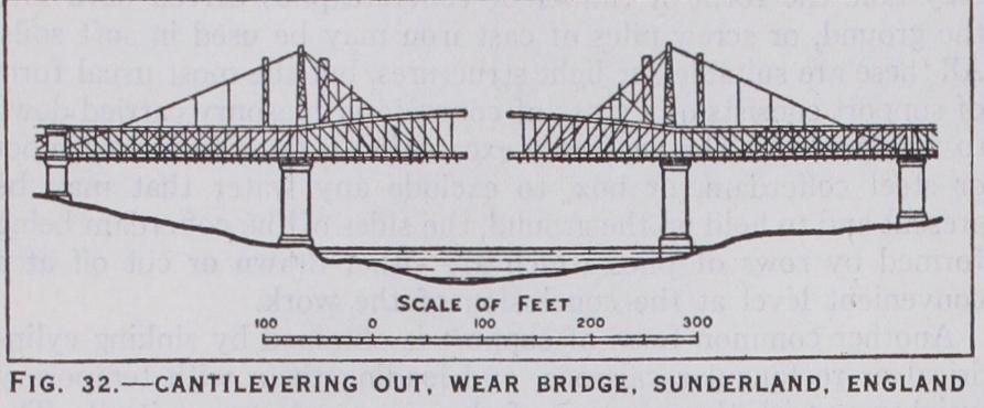
The cantilever type of bridge, by virtue of its shape and design, readily lends itself to this method of erection, which, however, can be applied to other types as well though temporary members have to be added. These usually consist of a mast placed over each abutment with ties from the top down to the shore, where an anchorage can be obtained, and to the projecting ends of the work. Independent and continuous girders and arches have all been erected in this way, though in many cases they have to be specially stiffened to resist the stresses temporarily set up during erection as they differ from the final stresses. In large structures, the changes of form, due to the stresses and to the temperature, have also to be taken into account and allowed for. One dis advantage of this method of erection is that it is difficult to supervise the men engaged in the work, and readjustments are difficult to make once a member is in position. Fig. 32 shows the roadway and railway bridge, over the River Wear at Sunderland, under erection. The work was of a heavy character, the stresses in the temporary back stays amounting to 1,200 tons, and special hydraulic jacks, capable of exerting a force of 1,600 tons, were used for adjusting them so that the two halves of the structure were in perfect alignment and level when they met.