
BARGE CANALS Choice of Line.—In laying out a line of canal the engineer is more restricted than in forming the route of a road or a railway. Gradients being inadmissible, the canal must either be made on one uniform level or must be adapted to the general rise or fall of the country through which it passes by being constructed in a series of level reaches at varying heights above a datum line, each closed by a lock, or some equivalent device, to enable vessels to be transferred from one to another. To avoid unduly heavy earth work, the reaches must follow the bases of hills and the windings of valleys, but from time to time it will become necessary to cross a depression by the aid of an embankment or aqueduct, while a piece of rising ground or a hill may involve a cutting or a tunnel. Sharp bends must be avoided, the permissible radius of curves depending on the dimensions of the vessels for which the canal is designed and the width of the waterway.

Some economy of water in locking may be effected by using side ponds (see below) ; but, nevertheless, it is necessary in the case of some canals to resort to pumping in order to supply de ficiencies, particularly in dry seasons and on summit levels. There are many canal pumping installations in France, Germany and England. Electric power has been utilized for pumping in some plants.
Safety or stop-gates are necessary at intervals for the purpose of dividing the canal into isolated reaches so that, in the event of a breach, the gates may be shut, and the discharge of water confined to the reach intercepted between two of them. In broad canals these stop-gates may be formed like lock gates ; or in small works they sometimes consist of thick planks slipped into grooves. Self-acting gates have been tried but have not proved trustworthy. Stop-gates consisting of a horizontally framed steel shutter of the width of the canal, suspended from an overhead bridge and counterbalanced, are used on some modern canals: these can be lowered by means of gearing into grooves built in the canal sides.
The gates, generally of oak in old canals, but more usually of steel in large canals and those of later date, fit into recesses of the walls when open, and close against sills in the lock bottom when shut. In small narrow locks single gates only are necessary; in large locks pairs of gates are required, fitting together at the head or "mitre-post" when closed. The vertical timber at the end of the gate is known as the "heel-post," and at its foot is a casting that admits an iron or steel pivot which is fixed in the lock bottom, and on which the gate turns. Iron straps round the head of the heel-post are let into the lock-coping to support the gate. The gates are opened and closed by balance beams project ing over the lock side in the case of many small locks and by hand gearing in others. Electrically operated machines are largely employed on canals of modern construction in America and on the continent of Europe for opening and closing lock gates and sluices. (See also DocKs.) In order to economize water, canal locks are made only a little larger than the largest vessel they have to accommodate (see below: Canal Barges and Modern Canal Development). In many canals constructed since 1900, however, provision is made for admitting a train of barges; such long locks have sometimes intermediate gates by which the effective length is reduced when a single vessel is passing (fig. 6) .
The lift of canal locks, i.e., the difference between the levels of adjoining reaches, rarely exceeded 12ft. up to the end of the 19th century and in some locks the lift is as little as i If t. The modern practice is to build one lock with high lift in preference to a flight of shallower locks in all cases where the configuration of the ground and considerations of water supply allow of this being done. In Germany, for instance, there is at least one lock with a lift of over 65f t., and lifts of 20 to 4oft. are not uncommon in America and on the continent of Europe.
To save water, especially where the lift is considerable, side ponds are sometimes employed. They are reservoirs into which a portion of the water from a lock-chamber is run and stored in stead of being discharged into the lower reach, and it is used once more for partially filling the chamber. The consumption of water is in some cases reduced by this means by 50%. Double locks, may also be used to save water, since each serves as a side pond to the other, and to save time, since vessels can pass up and down simultaneously.
At Anderton a lift was erected in 1875 to connect the Weaver navigation with the Trent and Mersey canal, which at that point is 5oft. higher than the river. The lift is a double one, and can deal with barges up to 10o tons ; the vessels are water-borne in a wrought-iron tank 7 Sf t. long and 15 if t. wide. Until 1908 the tanks were raised and lowered by means of hydraulic rams but in that year electric power was substituted, each of the two tanks being counter-balanced by weights and operated by electric winches. (See J. A. Saner, Proc. Inst. C.E., vol. clxx., 1910.) A similar hydraulic lift, completed in 1888 at Fontinettes on the Neuffosse canal in France, can accommodate vessels of 30o tons, a total weight of 785 tons being lifted 43ft.; and a still larger example on the Canal du Centre at La Louviere in Belgium, built in 1888, has a rise of soft., with tanks that will admit vessels up higher end and re-entering the river at its lower end or vice versa. There are many examples of lateral canals in Canada, notably those connected with the river St. Lawrence, also in the United States and on the continent of Europe, particularly in France.
The La Louviere lifts are the only examples constructed in Europe since 1899, when the Henrichenburg lift on the Dortmund Ems canal was opened. The latter raises barges of 60o tons carry ing capacity through a height of 46 feet. The single tank is 223 x 28ft. internally, the depth of water being 8 feet. The operation of the lift is effected by an ingenious arrangement of balancing floats immersed in deep tank-shafts. At Peterboro, Ontario, there are two hydraulic barge-lifts constructed about 1908. Neither lifts nor inclines are in use in the United States.
Generally speaking, canal constructors, both in America and on the continent of Europe, have, for many years, shown a decided preference for high-lift locks to either mechanical lifts or inclines.
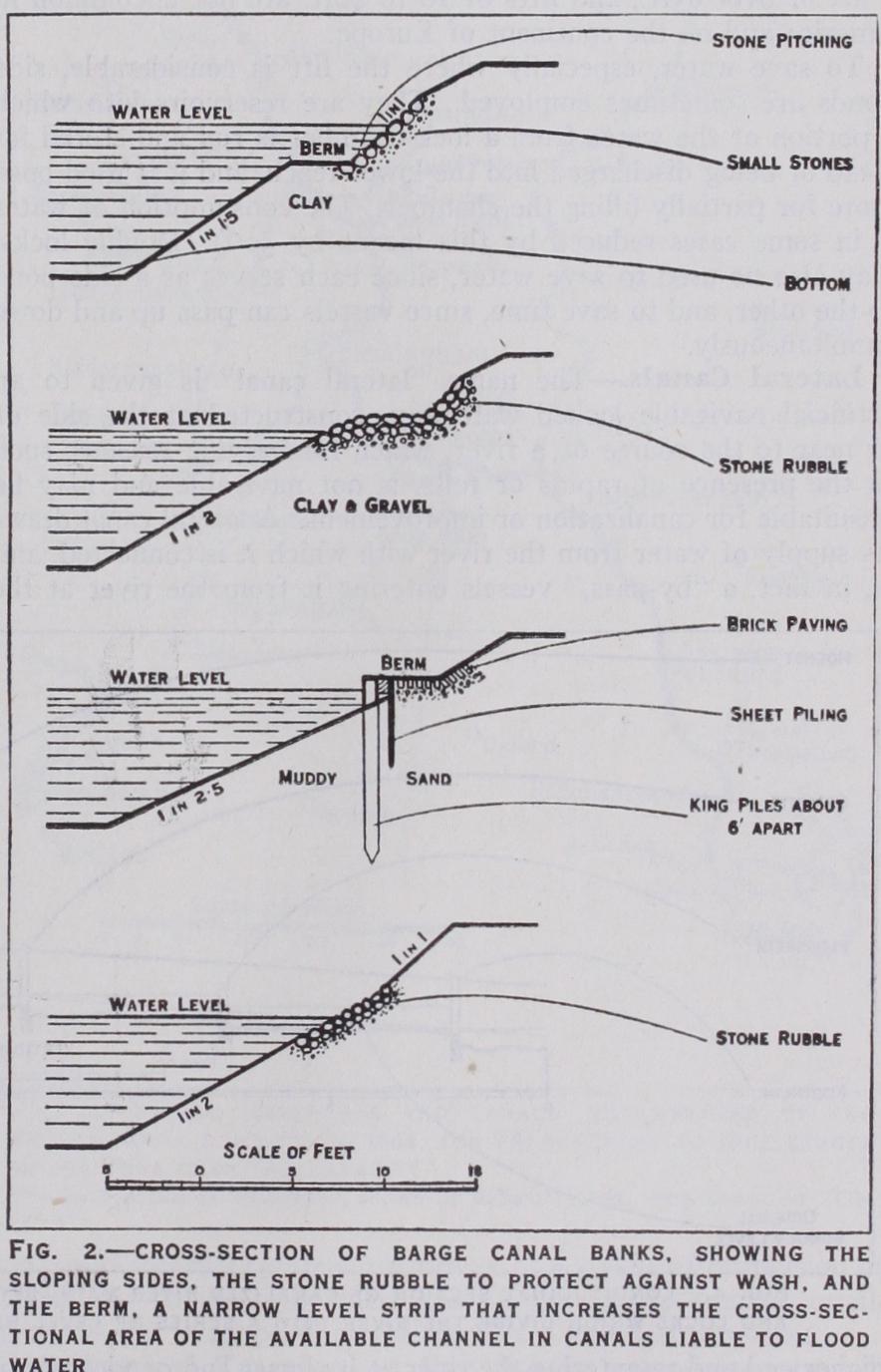
At speeds over c. 3m. per hour the "wash" of the barge begins to cause erosion of the banks and thus necessitates the em ployment of protective measures which are commonly provided in all canals of modern construction (see above). Moreover the tractive effort required to haul a barge increases with the speed at a rate which much exceeds a direct proportion; and careful trials carried out in France and Germany since 1909 show that, on barge canals, a speed greater than 3m. or 3-1m. per hour is uneconomical as regards both haulage and maintenance costs. The speed on French canals is limited to five km. (3.11m.) per hour; and a tug or tractor with its tow of barges usually does from 13 to 18m. per day on the average (including going through locks). The speed limitations (1928) on German, Belgian and Swedish canals are on a par with the French. It may be noted in passing that, in towing or hauling barges on a canal, the tractive force per barge decreases with the number of barges in tow.
On the Aire and Calder navigation, where the locks have a minimum length of 21 sf t., a large coal traffic is carried in trains of boat-compartments. The boats are nearly square in shape, ex cept the leading one which has an ordinary bow. They are coupled together so that they can move both laterally and vertically ; and a wire rope in tension on each side enables the train to be steered. No boat crews are required, the crew of the tug regulating the train. Each compartment carries 35 tons, and the total weight in a train varies from 700 to 90o tons. On the arrival of a train at Goole the boats are detached and discharged into sea-going ships by means of cradles and hydraulic hoists.
Barges self-propelled by steam-power were first tried on the Forth and Clyde canal by Symington as early as 1789. Since 1910 the use of internal combustion motors as a means of propulsion on canals has considerably increased. Even on the smaller canals many barges in all parts of the world are now self-propelled.
Mechanical Traction on Canals.—In several long tunnels and deep rock cuttings in France where no towpaths have been provided, recourse has been had to a submerged chain which is passed round a drum on a tug; this drum is rotated by steam power and thus the tug is hauled through the reach. The same system is in use on the Regents Canal (London) for towing barges through the Islington tunnel. In the Mont-de-Rilly tunnel, at the summit level of the Aisne-Marne canal, a system of cable-traction was established in 1893, the boats being taken through by being attached to an endless travelling wire rope supported by pulleys on the towpath.
Small locomotives running on rails along the towpath were tried, towards the end of the 19th century, on the Shropshire Union canal, where they were abandoned on account of practical difficulties in working. About the same time similar experiments were made on canals in France and Germany, where, however, the financial results were not satisfactory. On portions of the Teltow canal, joining the Havel and the Spree, electric tractors run on rails along both banks, taking their current from an over head conductor; they attain a speed of an hour when hauling two 600-ton barges. Electricity is also utilized for working the lock gates and for various other purposes along the route of this canal. Electric tractors are also employed on the Charleroi canal (Belgium), and petrol tractors on the Bourgogne canal (France).
Since about 1923 on the Canal du Nord, between St. Omer and Janville, electric tractors running on rails on the bank haul 300 ton barges in groups of two or more. On the Calais-St. Omer section light caterpillar road tractors of the Citroen type were established in 1925 for hauling two or more loaded barges. Elec tric rail tractors are also employed on sections of the St. Quentin and other canals in the north of France, and were experimented with on the Liege-Antwerp canals in Belgium in 1919, but soon abandoned. Mechanical traction has not developed in so marked a manner as towage; and, on the whole, the results do not show any considerable decrease in cost compared with other haulage or towage, nor has the speed of the boats been materially increased. The cost of installing and working a system of electric rail trac tion is only justified in cases where, as on some of the canals in the north of France, the traffic is intense ; on the St. Quentin canal the traffic intensity before the war amounted to between six and seven millions of tons per annum and in 1926 had nearly returned to six millions. On the Nord system light tractors are preferred for the less busy sections. Electric capstans are provided at many French and a few Belgian and Dutch canal and river locks for facilitating the passage of barges. In some cases little use appears to be made of these facilities.