GAS ANALYSIS The general principles involved in the various processes of gas analysis are best exemplified by a consideration of the quanti tative estimation of the constituents of fuel gases, such analytical tests being the chief task of gas examiners. Gasometric methods are, strictly speaking, branches of volumetric analysis, one of the main divisions of quantitative work.
The composition of a gas is usually expressed in percentages by volume, as it is easier to measure a gas than to weigh it. As, however, the volume of a gas depends upon its temperature, pressure and moisture content, all volumes must be compared at the same temperature and pressure and further must be either dry or fully saturated with moisture ; if the conditions under which they are compared are not the same, the volumes in each case must be referred to a standard condition. The standard usually em ployed is the International Standard, in which all volumes are referred to the dry volume which the gases would occupy at o° C and 76omm. of mercury pressure. If V is the volume of a gas saturated with moisture measured at t° C and hmm. of mercury, and a is the vapour pressure of water at t° C (obtained from tables), then the volume V. at the standard conditions is given by the equation Vo=V (h—a) 273/760(273+t). In Great Britain the gas industry is bound by statute to use a different standard, namely the volume saturated with moisture at 6o° F and 3oin. of mercury pressure. Thus if V is the volume at t° F and hin., the vapour pressure of water at t° F being a, then the volume under standard conditions is Vo=V (h—a) r 7.64/(460+t). Tables to facilitate these calculations are given in text-books of gas analysis.
The volumetric analysis of a gas is usually carried out on a small quantity, ranging from 5 to Ioo cu.cm., and if this small sample is to be representative of a large bulk of gas, special pre cautions must be taken to ensure that the sample is properly taken. Whenever the analysis of a sample of gas cannot be made at the place where it is collected, it must be stored in a sample tube with well-fitting glass taps. If the sample is to be kept for some time, it is preferably preserved in a glass tube with sealed ends.
The methods employed in the volumetric analysis of gases are based on: (I) Successive absorption of the constituents by suit able reagents each of which absorbs one only; (2) burning the gas with air or oxygen and measuring the change in volume and the amount of carbon dioxide produced; (3) selective oxida tion by passing the gas over suitable reagents; e.g., heated copper oxide.
The following are typical analyses of fuel gases: Of these constituents carbon dioxide unsaturated hydro carbons (which include ethylene, propylene and benzene), oxygen and carbon monoxide (CO) are estimated by absorption methods; and hydrogen (H_), methane (CH,) and sometimes carbon monoxide by combustion methods. The nitrogen is usually obtained by difference.

The absorbents used are (I) 25% aqueous solution of caustic potash for carbon dioxide ; (2) bromine water or fuming sulphuric acid for unsaturated hydrocarbons. In either case these reagents must be followed by an absorption with potash to remove vapours evolved by bromine and sulphuric acid ; (3) stick phosphorus m a solution of potassium pyrogallate (I og. of pyrogallic acid dis solved in ioo cu.cm. of saturated caustic potash) for oxygen; (4) acidic or ammoniacal cuprous chloride solution for carbon monoxide—the latter is preferable and is made by mixing 'vol. of ammonia (sp.gr. 0.905) with 3vol. of a solution containing cuprous chloride 2oog., ammonium chloride 250g., water 750g. Two absorptions must be made with the cuprous chloride solu tion, the last one being with a fresh solution. Alkaline pyrogallate and cuprous chloride solutions, which become oxidized and lose their absorbing capacity when exposed to the air, must be stored in the double type of pipette if the Hempel apparatus is being used, the two exterior bulbs being filled with water to prevent access of air.
Certain reagents will remove more than one constituent from the gas so that the order in which the absorptions are made is very important. If the unsaturated hydrocarbons are to be re moved by bromine water, the sequence is as follows : carbon dioxide by potash, unsaturated compounds by bromine, oxygen by phosphorus or pyrogallate, carbon monoxide by cuprous chlo ride. On the other hand, if fuming sulphuric acid is used in place of bromine the order must be : caustic potash, pyrogallate (not phosphorus), fuming sulphuric acid, cuprous chloride. Phosphorus will not remove oxygen from the gas if unsaturated compounds are still present; it is also very slow in action if the temperature of the gas falls below 18° C.
The contraction observed and the carbon dioxide produced when hydrogen and methane are burned together with a known excess of oxygen or air, give a means by which these two gases may be determined, whereas the residual nitrogen is estimated by difference.
When burned with an excess of air or oxygen, 'vol. of hydrogen combines with ivol. of oxygen to form water, which is condensed, so that there is a contraction of z vol.: With methane the reaction is i.e., I vol. of methane combines with 2 vol. of oxygen, forming i vol. of water vapour (which is condensed) and i vol. of carbon dioxide; the contraction is therefore 2 vol. and the carbon dioxide produced is equal in volume to the methane present. When a mixture of the two gases is burned, the methane is A and the hydrogen (C-2A), where C is the contraction on burning or exploding and A is the volume of carbon dioxide formed.
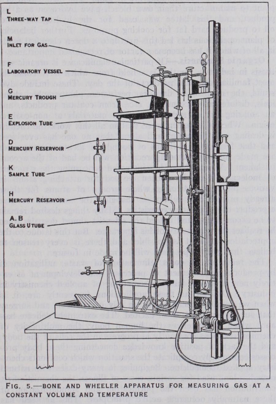
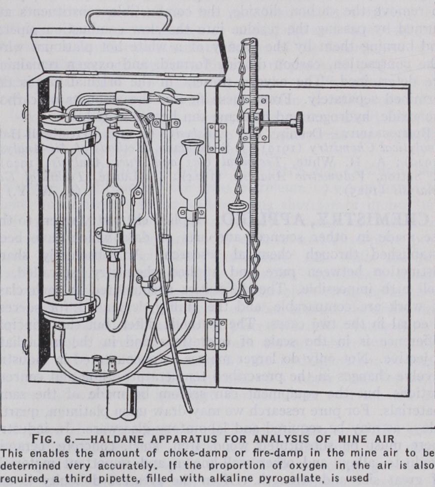
Of the many forms of gas apparatus recommended for these analyses three will now be described in detail—the Hem pel apparatus as a type in which the volume of the gas is measured at con stant pressure, the Bone and Wheeler ap paratus as an example of those in which the pressure of the gas is measured at constant volume and the Haldane ap paratus, employed when some of the im portant constituents are present in very small amounts.
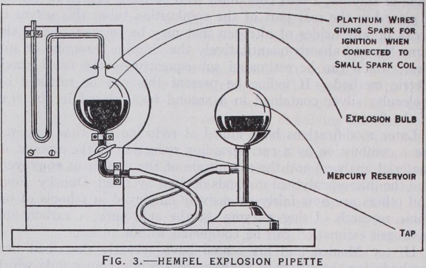
Hydrogen and methane are estimated in the residual gas by diluting 15 or 20 cu.cm. to I00 cu.cm. with excess of air or oxygen and exploding the mixture under reduced pressure over mercury in the explosion pipette. This pipette (fig. 3) is provided with a pair of platinum sparking points which are connected to a small induction coil, and the reduction of pressure is effected by lower ` ing the mercury reservoir which is connected by thick-walled rubber tubing to the pipette. The gas is then returned to the burette and the contraction measured. The carbon dioxide formed is absorbed in the potash pipette and this second contraction measured. The hydrogen and methane present in the small amount of residual gas taken for the explosion can be calculated from the formulae given above, and hence the percentages in the original gas are calculated.
The combination of hydrogen, methane and oxygen can be ef fected without explosion by passing them at a suitable dilution into a pipette filled with mercury provided with a short length of platinum wire which can be heated by passing an electric current from dry cells or an accumulator.
Hydrogen can be determined in the presence of methane by passing a mixture of the gas and air through a capillary tube containing palladium wire or palladium-asbestos. The gas is passed several times backwards and forwards from the burette through the gently heated tube into a pipette containing water.
The nitrogen remaining is often determined by difference, but it is advisable to check it by a more direct method. For this pur pose a fresh sample of the gas is circulated through a silica tube filled with copper oxide heated to bright redness, and is passed into a pipette filled with caustic potash solution. The whole of the gases present with the exception of the nitrogen are burned to carbon dioxide and water, both of which are absorbed in the potash. The operations are continued until the volume of the residual gas is constant, and a correction is applied for the air originally contained in the silica tube.

The Hempel apparatus is not portable, but a modification known as the Orsat apparatus (fig. 4) is portable. This resembles the Hempel in principle and use except that the pipettes are perma nently attached to the burette by a glass capillary tube and taps. When the apparatus is intended for the analysis of flue gases only, three pipettes are provided filled with caustic potash, alkaline pyro gallate and cuprous chloride, respectively. A bromine pipette and a palladium-asbestos tube are sometimes added. The carbon monoxide found will always be too low as only one pipette is employed for the cuprous chloride.
It has been assumed up to the present that the gases analysed are completely insoluble in water ; and with the exception of car bon dioxide, which is appreciably soluble, the assumption is cor rect enough for ordinary purposes. To avoid loss of carbon dioxide, the water is of ten saturated with the gas to be analysed ; or for more accurate work the water is replaced by mercury. The Sodeau apparatus is based on the same principle as the Hempel arrangement but employs mercury.
In the methods so far described the volume of the gas has been measured at a constant pressure and temperature. The alternative principle of measuring the gas at a constant volume and tempera ture can be equally well employed. This method has the advantage that 5 or io cu.cm. of gas can be expanded to give a pressure of r oomm. and that all the measurements are independent of the barometric pressure.