
TIONS; COLLIERY OUTPUTS The opening and laying out of a colliery is rarely undertaken without a preliminary examination of the character of the strata by means of borings, either for the purpose of determining the number and nature of the coal seams in new ground, or the posi tion of the particular seam or seams which it is proposed to work in extensions of known coalfields.
Determination of Depth and Dip of Coal Seams.—The principle of proving a mineral field by boring, in the case where the true dip of the measure is known, is illustrated by fig. 7, which represents a line direct from the dip to the rise of the field, the inclination of the strata being one in eight, which is about 7° or 4.5in. to the yard. No. I bore is commenced at the dip, and reaches a seam of coal (A) at 4o fathoms, or 24oft. At this depth it is considered proper to remove nearer to the outcrop so that lower strata may be bored into at a less depth, and a second bore is commenced. To find the position of No. 2, so as to form a continuous section, it is necessary to reckon the inclination of the strata, which is I in 8 ; and as bore No. I was 40 fathoms in depth, we multiply the depth by the rate of inclina tion, 4oX8=32o fathoms, or I,92oft., which gives the point at which the coal seam (A) should reach the surface. But there is generally a certain depth of alluvial cover which requires to be deducted, and which we call 3 fathoms, then, fathoms; or, say, 296 fathoms is the distance that the second bore should be placed to the rise of the first, so as to have, for certain, the seam of coal (A) in clear connection with the seam of coal (B). In bore No. 3, where the seam (B), according to the same system, should have been found at or near the surface, another seam (C) is proved at a considerable depth, differing in character and thickness from either of the preceding. This derangement being carefully noted, another bore to the outcrop on the same principle is put down for the purpose of proving the seam (C) ; the nature of the strata at first is found to agree with the latter part of that bored through in No. 3, but immediately on crossing the dislocation seen in the figure it is changed and the deeper seam (D) is found.

The evidence therefore of these bores (3 and 4) indicates some material derangement, which is then proved by other bores, either towards the dip or the outcrop, according to the judgment of the borer, so as to ascertain the best position for sinking pits. (See BORING.) Winning the Seam.—The working of coal may be conducted either by means of levels or galleries, known as adits, driven from the outcrop in a valley, or by shafts or pits sunk from the surface. In the early days of coal mining, open working or quarry ing from the outcrop of the seams was practised to a considerable extent; but there are now few, if any, places in Great Britain where this can be done. (See article on Aim.) In Great Britain, every coal mine has—unless exempted under certain conditions— to be provided with two shafts or outlets, affording separate means of ingress and egress, not less than 15 yd. apart, and hav ing between them a communication of not less than 4ft. by 4ft.
The operations by which the coal is reached and laid out for removal are known as "winning," the actual "working" or ex traction of the coal being termed "getting." A seam of coal is said to be won when the shafts reach it. The process of sinking the shafts is treated under a separate article to which the reader is referred. (See article SHAFT SINKING.) Opening Out the Mine.—The shafts having been sunk and equipped, and the method of working having been decided upon, it is necessary to arrange for the lay-out, namely, the formation of the shaft inset, the size of the shaft pillars, the position of the shaft sidings, the making of the stables for the horses and ponies, and the number and position of the main roads.
The laying out of a colliery of ter the coal has been won, by sinkings or levels, may be accomplished in various ways, accord ing to the nature of the coal, its thickness and dip, and the ex tent of ground to be worked. In parts of the South Staffordshire and other coalfields, where only shallow pits are required, a pair of pits may be sunk for a very few acres, while on the other hand where sinking is deep and consequently expensive, an area of some thousands of acres may be commanded from a couple of pits. In the latter case, which represents the most approved practice, the sinking is usually placed about the centre of the ground, so that the workings may radiate in every direction from the pit bottom with the view of employing the greatest number of hands to advantage. Where a large area cannot be commanded, it is best to sink to the lowest point of the field for the convenience of drawing the coal and for drainage of water. It is necessary to maintain a thick barrier of unwrought coal between the boundary of the mine and the workings of a neighbouring colliery, especially if the latter are to the rise. If a prominent line of fault crosses the area it may usually be a convenient division of the fields into sections or districts.
The first process in laying out the workings, if the seams are only moderately inclined, consists in driving levels in the coal seam from both sides of the shaft, which, having proceeded a suf ficient distance, the "shaft pillars" are formed. These consist of large pillars of coal which are left unworked as a support to the shaft until the mine is worked out, when they are then worked off. (The arrangement of these pillars and of the main roads are illustrated in the article AIRWAY, to which the reader is referred.) This pillar is known in Scotland as the "pit bottom stoop." The junction of the levels with the pit is known as the "pit eye"; it is usually of an enlarged section, and lined with masonry or brick-work, so as to afford room for handling the trams (tubs, boxes, hutches) of coal brought from the working faces. In this portion of the pit are generally placed the hauling engine and the stables.
By the British Coal Mines Act of 191 I it is required that, in all mines opened after the commencement of that act, there shall be two main intakes—there are exemptions from this provision in certain exceptional and specified cases—of such size and main tained in such condition as to afford a ready means of ingress to and egress from the workings. Only one of these roads can be used for the haulage of coal. The distance from the downcast shaft, within which the two main intakes shall not be required to be provided, is the distance between the shaft and the edge of the shaft pillars (see fig. 8), and in the case of an inclined shaft or level entrance not driven in the coal seam, the distance shall be the distance between the point where the shaft or entrance strikes the seam and the edge of the pillar left to support the in cline or entrance. If driven in the coal seam, the distance is 2ooyd. from the mouth of the entrance.
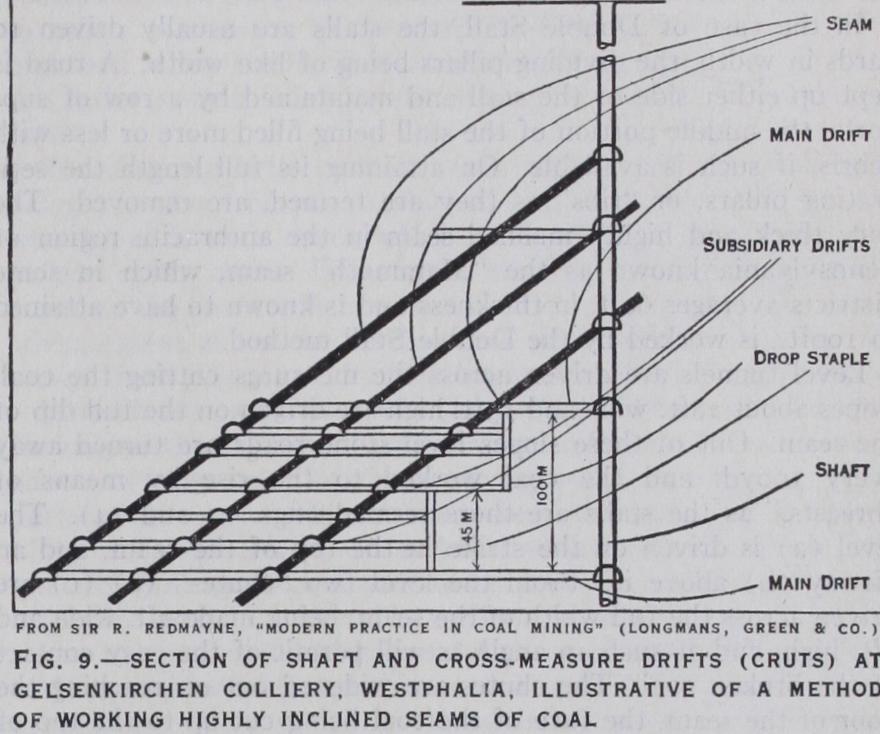
When the seams sunk to are highly inclined, they are won by driving from the shafts "cross-measure" or "level stone" drifts— or "cruts," as they are called in the steep or Rearer working (see next section) of North Staffordshire. This is shown in fig. 9, which is a section of shaft and the roads immediate thereto at Gelsenkirchen colliery, Westphalia, illustrating an arrangement of cross-measure drifts and subsidiary drifts, connecting the work ings in highly inclined seams with the shafts. Fig. I o is a section of a subsidiary drift at the same colliery.
In the Bord and Pillar system the field is divided into strips by numerous open ings or excavations called "bords" (i.e., roads) driven at right angles to the main cleavage or "cleat," these openings being again divided by cutting through them at intervals with roads termed "walls" (which are parallel to the main cleavage or cleat), so as to leave a series of pillars arranged chequerwise over the entire area. The pillars are left for the support of the roof as the workings advance, so as to keep the mine open and free from waste. In the oldest form of this class of working, where the size of the pillar was about equal to the width of the "bord," from 50-7o% of the whole seam was removed, the re mainder being left in the pillars. Pillars are now made much larger than formerly; 2 2yd. X 44Yd•, 44Yd• X 44Yd., or even 44yd. X 66yd. are frequent sizes, and the "bords" are made 5-6yd. wide, the "walls" 2 to 3 yards. (See BORD AND PILLAR.) In the formation of the pillars (the first working, or working "in the whole" as it is technically termed) a much less percentage of coal is got than in the removal of the pillars (the second or "broken" working), and the coal is usually, unless the pillars are crushed, smaller in size and the output per man less owing to blasting being generally necessary, especially if the coal seam be hard in character. If the pillars are too small or are irregularly removed, a "creep" is liable to set in, especially if the floor be soft ; that is, the pillar will be forced into the floor owing to insuf ficiency of support offered to the superincumbent strata.
A coal seam with a soft pavement (floor, thill, spavin) and a hard roof present the conditions most favourable to "creep," the first indication of which is a dull hollow sound heard when tread ing on the pavement or floor, occasioned by some of the individual layers parting from each other as shown at (a) fig. I I ; the suc ceeding stages of creep are shown at (b) (c) (d) (f) and (g) in the same figure; the last being the final stage, when the coal be gins to sustain the pressure from the overlying strata, in common with the disturbed pavement.
"Thrusts" or "sits" are the reverse of creeps ; in the one case the pavement is forced up, in the other the roof is forced or falls down for want of proper support, or tenacity in itself. This acci dent generally arises from an insufficient size of the pillars ; some roofs, however, are so difficult to support that thrusts take place where the half of the coal is left in pillars. Fig. I 2 will convey a general idea of the appearance of thrust—(k) (m) (n) showing different stages.
In the modern method of pillar working, as carried out in the Durham and Northumberland districts, the "bords" usually are from 5 to 6yd. wide, while the pillars are 22yd. broad and 3oyd. long or larger, which are subsequently got out on coming back; or the "whole is followed up with the broken," that is to say, the pillars are removed contemporaneously with the projection of the "whole" workings, though well to the rear of them ; a barrier of two or three ranges of pillars being left between the "working in the solid" or "whole," and the pillars which are being worked off. The space from which the entire quantity of coal has been re moved is known in different districts as the "goaf," "gob" or "waste." Modifications of the Bord and Pillar.—The modifications of Bord and Pillar working practised in Great Britain, and abroad also, are those known in Great Britain by the names of (I) Single and Double Stall, (2) Wide or Square work, and (3) Rearer workings. The first named is chiefly practised in South Wales, more particularly in the working of the anthracite seams and the "dry" steam coals, though even in the latter the Longwall method (see subsequent section) is adopted wherever practicable. The wide or square work is restricted to the working of the Thick or Ten Yard coal of South Staffordshire. The rearer working, which is a method of working highly inclined seams, is peculiar to North Staffordshire.
In the Stall working, or "bord and banks," as it is termed when practised in Yorkshire, where support is required to buildings, rail ways or reservoirs, the "stall" or "bord" is much wider, as well as the pillars or "banks," than in South Wales. In the South Wales case the levels are driven on the strike of the seam and out of these, at intervals of i syd., stalls 5-6yd. wide at their full width are turned away and advanced on the full rise of the seam. When the stalls have attained their limit in length, a factor which will be governed largely by the character of the floor and roof, the pillars separating the stalls will be worked off. The "double entry" method of working in the United States of America is practically the same method.
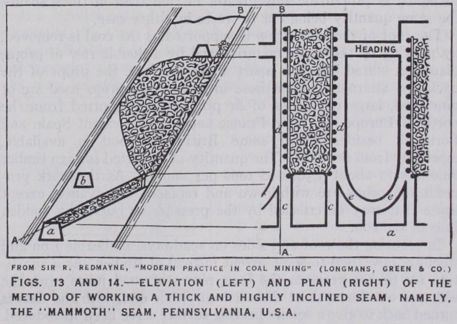
In the case of Double Stall, the stalls are usually driven ro yards in width, the dividing pillars being of like width` A road is kept up either side of the stall and maintained by a row of sup ports, the middle portion of the stall being filled more or less with debris, if such is available. On attaining its full length the • sep arating pillars, or "ribs" as they are termed, are removed. The very thick and highly inclined seam in the anthracite region of Pennsylvania known as the "Mammoth" seam, which in some districts averages 6oft. in thickness and is known to have attained to i oof t., is worked by the Double Stall method.
Level tunnels are driven across the measures cutting the coal, slopes about 28ft. wide and rsft. high are driven on the full dip of the seam. Out of these slopes level stone roads are turned away every iooyd. and the coal worked to the rise by means of "breasts," as the stalls are there termed (figs. 13 and 14). The level (a) is driven on the strike in the top of the seam, and an airway (b) above it. From the level two "chutes" (c) (c) are driven across the full width of the seam, being made 9f t. wide and 6ft. high, and at such an angle as will permit of the easy contact of the broken coal. The chutes are widened out on reaching the floor of the seam, the face of the coal being cut up to the top of the seam, as shown in the figure, and the breast advanced upwards. The distance between the chutes is about 3o feet. Through the pillar separating the stalls are driven the manways (d) with branches (e) (e) right and left connecting the two manways, which are supported by timber (fig. 15) .
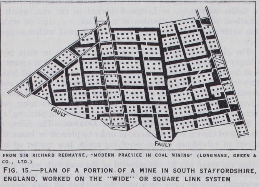
Perhaps the Wide or Square work as practised in South Staf fordshire for getting the Thick or Ten Yard seam of that field is the method of working chiefly practised on an abnormally thick seam which is flat or of moderate inclination. Though it is prob ably one of the most wasteful of all methods now practised, and many modifications have been tried, it still proves the most effective method of working a seam under the peculiar conditions named.
The main roads having been driven out—in the lower part of the coal—to the boundary, and the branch or district roads turned away right and left and also driven to the boundary, the coal opened out by the latter is worked by dividing it into a number of large chambers termed in South Staffordshire "sides of work" (fig. i6). A side of work when completed will be 5oyd. or more square, each chamber or "side of work" being separated from an "ad joining" side by a barrier of coal 8–ioyd. wide, which is locally termed a "fire rib," the only openings between the chambers being those necessary for ventilation (see fig. 16). In forming a side of work the roof coal is cut down bed by bed according to the partings in the seam (for the thick coal of South Staffordshire consists of a series of closely as sociated coal seams, varying from 8 to 12 or r3ft., divided from each other by their partings, but making together one great bed from 15 to 36 or even in some cases 4oft. in thickness), small pillars being left for the support of the roof. _ On the abandonment of a side of work the roads penetrating the barriers for the purposes of entry, ventilation and haulage, and known as "bolt holes," are dammed off so as to prevent risk of spontaneous combustion, to which this seam is very liable. Years after, when the roof has subsided and there are settled con ditions of superincumbent strata, these abandoned sides of work are re-entered and the pillars recovered as far as possible. There may be even a third working for the recovery of the barriers; so that, although in the first working not more than from 4o-5o% of the coal be recovered, ultimately over a period of years, the loss of coal may not exceed io%. But the coal gotten in these later workings is frequently considerably crushed.
So far the workings subsequent to the first working have been confined to the "exposed" coalfield where the coal exists at shal low depths. The problem of recovery of the ribs and pillars when working at great depths in the ,"hidden" coalfield, where the coal measures are overlaid by the "Red" rocks as the Permian and Triassic systems are sometimes locally designated (e.g., at Bag geridge and Hamstead collieries, where, at the latter colliery, the coal lies in parts at a depth of over 7ooyd. from the surface), is as yet unsolved, for the crush will be very considerable.
Not only are very thick seams more dangerous to work than thin seams by reason of the diffi culties in the way of effective support of roofs and sides and from liability to spontaneous combustion, but the coal is gotten at a higher cost per ton than in the case of seams of moderate thickness, as for instance 5 to 7 feet. When thin seams or seams of moderate thickness are highly inclined, they are usually worked by the Rearer method or by the Longwall system, e.g., Bristol method, Scotch method or the Belgian and French methods, tailles chassantes or tailles montantes.
The Rearer method consists in laying out the mine in "panels" or districts of pillars to the rise from off the main roadways, which are driven on the "strike" or level course of the seam. The chief novelty of the system consists in the manner of work ing off the pillars which is commenced as soon as the panel reaches the barrier. The pillar is "entered up," that is, worked off in stages (or "shoulders," as the cuts are termed locally) in an up ward direction, the angle of the workings being kept at about 45°. The coal falling into the level is drawn away and lowered down the incline, which constitutes the self-acting incline haulage road of the panel, on to the main level, along which it is hauled to the shaft. Scaffolding has to be erected to enable the miners to work and to protect them against falls, but ultimately, if the pillar being removed is below the goaf or gob, on breaking through into the goaf above it gradually fills up the excavated space and affords standing room for the coal hewer. The loss of coal in this method of working is very heavy by reason of crush and unrecoverable barriers and pillars. It has been estimated that not more than 6o% of the available coal is recovered and raised to the surface.
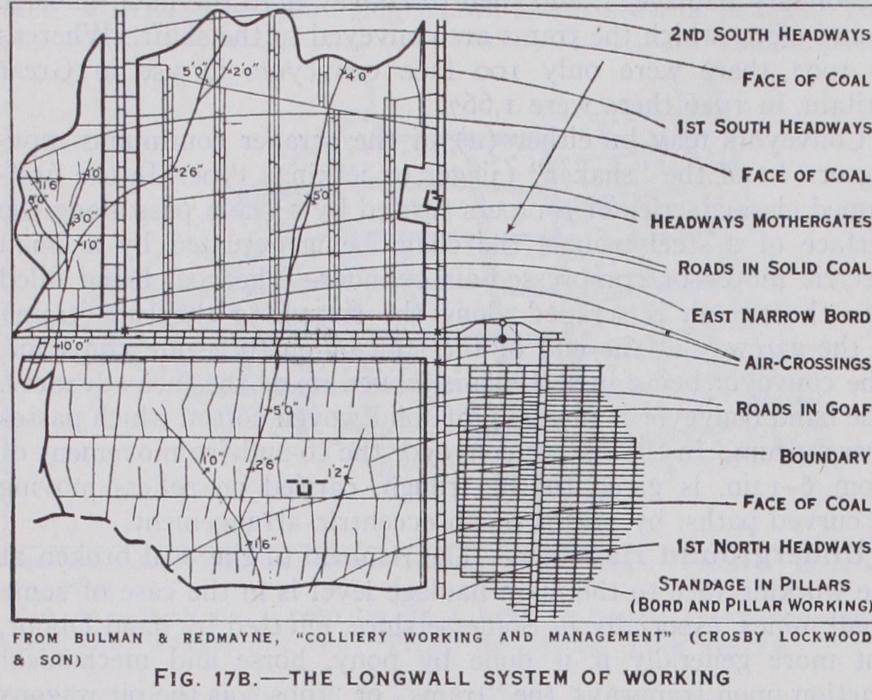
The general character of a long-wall working is shown in fig. I7B, which represents an area of about 5ooac. of hard steam coal. The principal road extends from the shafts southward ; and on both sides of it the coal has been removed from the light-shaded area by cutting it back towards the boundaries, along faces about 5oyd. in length, those nearest to the shaft being kept in advance of those farther away, producing a step-shaped outline to the face of the whole coal. It will be seen that by this method the whole of the seam, with the exception of the pillars which are sometimes left to protect the main roadways, is removed in one working. Where coal is left for the support of the main roads, it is recov ered when the field has been worked to its boundaries, but more commonly the main roads are made in the goaf. The roads for drawing the coal from the working faces to the main haulage road are kept open by walling through the waste or goaf produced by the fall of the unsupported roof and are cut off at intervals by crossgates. The direction of the air current is shown by arrows, the return air passing from the face into the return airways to the up-cast shaft.
This is the method of working "Longwall forward," i.e., taking the coal in advance from the pit towards the boundary, with roads kept open through the gob. An other method consists in driving towards the boundary and taking the coal backward towards the shafts, or working homeward, or "retreating Longwall," as it is technically termed, allowing the waste to close up without roads having to be kept open through it. This is of course preferable in many cases, though not always, but is only applicable where the owner of the mine can afford to expend the capital required to reach the limit of the field, in excess of that necessary when the raising of coal proceeds pari passe with the extension of the main roads, and where he is prepared to go a long time without receiv ing any return on his capital.
The above is the method practised in working a thin seam of coal or a seam of moderate thickness, i.e., from 'ft. 6in. to 7-8ft. in thickness, and that is flat or of moderate inclination. In Great Britain there are no very thick seams which are highly inclined; such thick seams as occur (e.g., south Staffordshire) are prac tically flat. But in the coalfield of St. Etienne, there is one seam in particular which is very thick and highly inclined, the Grande Couche by name, which reaches to 8of t. in thickness, with an inclination varying from 30°-90° from the horizontal.
The method by which the seam is worked consists in driving levels along the "strike" or level course of the seam, one above the other, which are connected by inclines, and the coal between the levels is worked out by means of either horizontal or inclined slices. Cross-cuts or level holings are driven to the "hanging wall" and the "foot wall," out of which the slices or "lifts" are taken, and the coal worked off, the excavated part being tightly packed with stone. The workings of each sub-stage rest on the packing of the sub-stage below it, the sub-stages being worked in ascend ing order.
The coal concession is divided into "panels" or districts '3oyd. wide and an inclined plane made in the middle of it, and one on either side from the bottom main level to the bottom of the first or top stage, the level in each sub-stage being turned away out of the middle incline and holed into the side or airway inclines, which secures the proper ventilation of the panel. It will be seen that the method is really a modification of the Longwall system.
The following instances of the Longwall system as applied to the working of thin seams or seams of moderate thickness where highly inclined, may be given as severally descriptive of the pro cedure in Scotland, Belgium and France respectively.
Scotland.—In the case under consideration, the seam is 2 ft. 4 in. thick, and its inclination from the horizontal 70°, the seam being won by cross-measure drifts driven out from the shafts to cut it. In the seam, levels are driven about every 3oyd. and the coal worked off the side as in "overhead" stoping in the case of metal liferous mining, up to the level above, the coal falling down shoots, spaced r 2yd. apart, into the level below. These shoots are about aft. sq. and are on the full rise of the seam and are "checked" (see fig. r 7A) in order to break the fall of the coal. The men travel to the face by way of the shoots.
Belgium and France.—Very similar to that described above is the method of working coal on the Continent in thinnish seams when having a steep dip (see fig. 18). The cross-measure drifts (etages) which are usually driven from the shafts at distances apart of 56 to 66yd., are about 'oft. wide by 9ft. high, the levels being driven in the seam right and left, one above the other, and connected by holings for ventilation purposes. The coal faces (maintenages), which are worked much in the manner of over head stoping, are stepped and the worked coal passed down coal shoots as shown. When the seams are not so steeply inclined, e.g., about and are very thin, i.e., under say 2 f t. 6in. in thickness, the system of working adopted is that termed tailles chassantes, i.e., Longwall worked on the level in contradistinction to tailles montantes, or Longwall worked to the rise, which is practised when the inclination is moderate, e.g., ro° or under, this latter system being purely ordinary Longwall with a stepped face.
The distance between each cross-measure drift or main level (etage) is about 6o yd. so that a width of coal to that extent is won by each main level, which is divided by three coal levels 20 yds. apart, one to each step or stall, by which the coal is con veyed to the shoot which carries it to the main level. The line of advancement is on the level course, the coal-getters being pro tected from falling coal by slanting boards shown in plan, fig. 19.
In a few anthracite collieries in America the small coal or culm and other waste are washed into the exhausted workings by water, which gives a compact mass filling the excavation when the water has drained away. A modification of this system is now largely employed elsewhere, e.g., France, Westphalia and Sumatra, but hardly at all in Great Britain owing to its cost. In this method the filling material, preferably sand, is sent down from the surface through a vertical steel pipe mixed with sufficient water to allow it to flow freely through distributing pipes in the galleries com manding the excavations to be filled ; these are closed at the bottom by screens of boards or brattice cloth, sufficiently close to retain the packing material, while allowing the water to pass by a lower level to the pumping-engine, which returns it to the surface. This is known as the "hydraulic" stowage of wastes. Where water is not available for the purpose, or cannot be used for other reasons, compressed air has recently been applied as the propelling agent in some German mines.
The process of holing in coal is one of the severest kinds of human labour. It has to be performed in a constrained position, and the miner sometimes lying on his side has to cut to a much greater height than is required to bring the coal down, in order to get room to carry the groove in to a sufficient depth, giving rise to waste in slack as compared with machine work. This is some times obviated by holing in a bed below, or even above, the coal, or in any portion of the seam of inferior quality, that may not be worth working, or in an interstratified band of dirt. The loss due to holing is proportionately greater in thin than in thick seams, the same quantity being cut to waste in either case.
The roof of the excavation is supported as the coal is removed, by packing up the waste material, and by a double row of props, placed at stated intervals apart along the face, the props of the back row alternating with those in front. The props used are of pinewood, large quantities of fir props being exported from the north of Europe and from France and to some extent Spain and Portugal, besides which some British pitwood is available, especially from Scotland. The quantity of imported foreign timber amounts to about 3,500,000 tons per annum. As the work pro ceeds the props are withdrawn and replaced in advance, except those that may be crushed by the pressure or buried by sudden falls of the roof.
In securing the roof and sides on roadways, malleable iron and steel are now used to some extent instead of timber. As a substi tute for timber props at the face, pieces of steel joists, with the web cut out for a short distance on either end, with the flanges turned back to give a square bearing surface, have been introduced. In large levels steel girders are sometimes used to support the roof, but in the smaller levels complete arches made of pieces of rails fish-jointed at the crown are used occasionally. In another system, introduced by the Mannesmann Tube Co., the prop is made up of weldless steel tubes sliding telescopically one within the other, which are fixed at the right height by a screw clamp capable of carrying a load of 15-16 tons. These can be most advantageously used in thick seams 6-1 oft. or upwards.
When driving the roads in "whole" working in the Bord and Pillar system, it is usually necessary to cut vertical grooves in the face at one side to determine the limit of the fall. This is known as "nicking." Where the coal is blasted down without "nicking" it is known as "shooting off the solid"; and where the coal is got without either "nicking" or "kirving," as "shooting out of the solid." Mechanical Coal Cutters.—The substitution of mechanical contrivances for hand labour in cutting coal has been a favourite problem with inventors. As far back as 1761, one Michael Menzies of Newcastle-on-Tyne devised a machine for cutting coal which was worked by man and horse ; but with the introduction of compressed air as a motive power in mines in 1855, a great impetus was given to machine cutters, and during the last 6o years great progress has been made. The writer of this article has particulars of the results obtained by a mechanical cutter at Elemore colliery in the county of Durham as far back as June and July 1865, and of Harrison and Frith's machines at Bishops Close colliery in the same county in Sept. 1865. Baird's machine, the "iron man" as it was locally termed, was one of the first machines applied. In March 1874 the cost of getting coal at Ele more Colliery by a mechanical cutter was 3s. 5d. per ton as against 35.4d. by hand, inclusive of cutting, putting and deputies, i.e. the total face cost of working. The machine employed was of the disc type and it was driven by compressed air.
Messrs. Gillot and Copley's (Barnsley) machine, also of the disc type, was working as far back as 1875 and had a great vogue for many years. It had two cylinders Tin. dia. 12in. stroke, driving a main shaft at a speed of ioo revolutions per minute. This shaft was connected by gearing with the cutting wheel or disc, fitted with zo teeth on its outer circumference, which were alternately single and double. This disc, which was 3ft. loin. dia. was placed horizontally, projecting from the bottom of the framework of the machine, and made six revolutions per minute. The machine under cut the coal to a depth of 3ft. 4in., the height of the cut being 4 inches. The machine was pulled along the face by a wire rope, one end of which was secured to the machine, the rope being carried along the face to a block fastened to a prop at the far end of the run, and returning to the machine was slowly coiled on a drum driven by the machine which ran on rails fixed in a thin iron sleeper. It was worked by compressed air, the pressure of which at the machine was 281b. per sq.in., and cut 7oyd. of face in four hours. The machine cost f 200. It will be seen that this machine, which did not differ materially from present day machines of the disc type, performed excellent work.
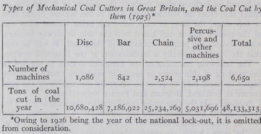
Mechanical coal cutters can conveniently be divided into five classes, viz., disc, bar, chain, rotary heading and percussive cutters. The extent to which these cutters are respectively used in the coal fields of Great Britain, and the quantity of coal cut thereby, is shown in the following table :— Out of a total of 2,840 mines in Great Britain included under the Coal Mines Act (some few of which are Cleveland iron mines producing no coal), at only 915 coal mines are mechanical coal cutters used. In some coal mines they cannot be used as the coal will not stay up to be holed, and in others the nature of the roof is such as to necessitate close propping, so that there is not room for machines to move along the face. Of the machines, are actuated by electricity and 3,516 by compressed air. About 20% of the national output of coal is got by mechanical coal cutters.
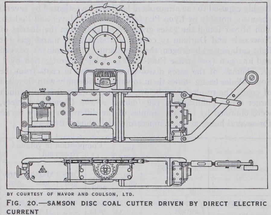
The construction of the disc type has already been de scribed, the modern machines of this kind differing but little from the machines originally made by Gillot and Copley, but "skids" or "sledges" have largely taken the place of rails for the travel of the machine. (See fig. 20.) In order to keep the machine up to its work and counteract the outward thrust, when the machine is on skids, steel blades are attached to one side of the frame which cut into the floor. A disc machine cannot cut itself into the face, so it is necessary to provide a side for it to cut in from. These sides are termed "rooms" or "stables." Some of these machines cut in for a dis tance of five feet.
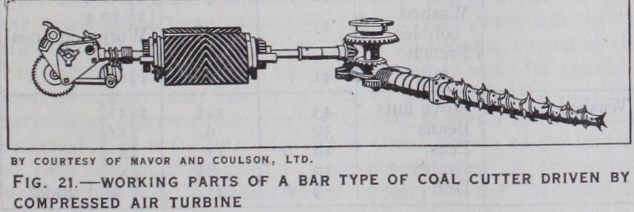
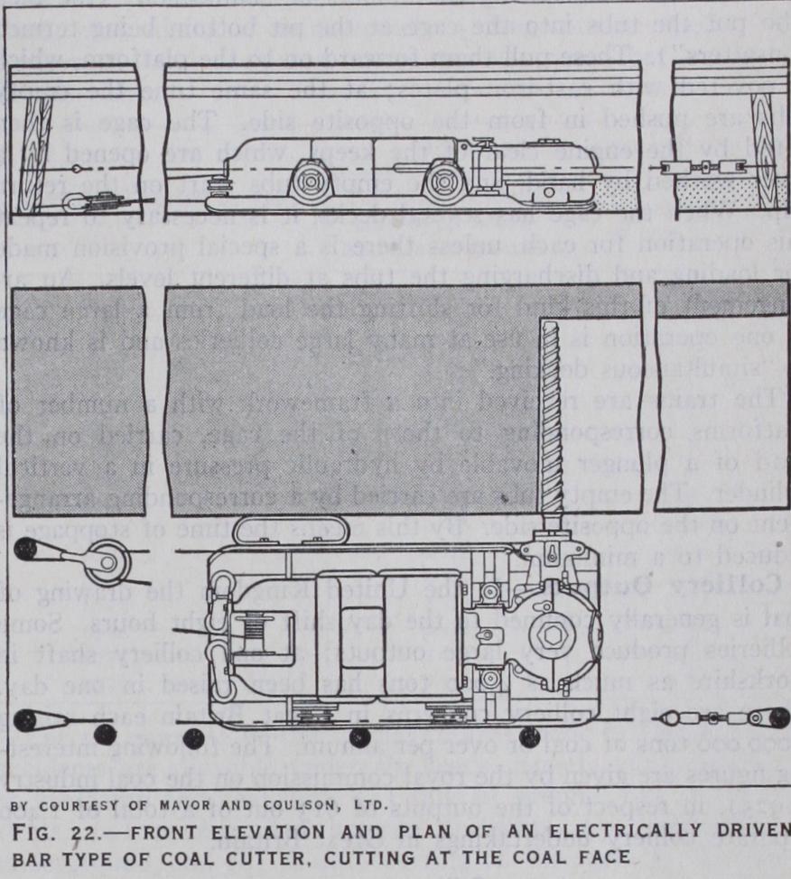
The Bar type (see figs. 21 and 22), consists of a bar, projecting from the frame of the machine, fitted with teeth, which is rotated by gearing. It is less powerful than the disc or the chain machine, but the bar, which is ta pered to a point, makes a thicker cut and removes more material than the other two types of rotated cutters, and though a less powerful machine, it has these advantages over the other types, that it cannot be jammed by falling material; the bar is easily swung in and out of the cut ; it cuts in either direction ; "stables" are not required as it cuts itself into the face ; "sprags" can be inserted close up to the cutting face. It is the most suitable ma chine for overcutting and deep cutting. (It has cut to a depth of 9 feet.) Its application is frequently well suited to cutting in a "band," if the latter is fairly thick. It has given good results in steeply inclined seams, and it is especially suited, as compared with the other rotating types, to working in a seam much dislocated by faults.
The Chain Machine (see fig. 23) consists mainly of a frame or "jib" 2ft. in width, projecting from the main body of the machine and carrying an endless chain having cutting teeth. It is fitted with a single bevel-gear reduction from the motor to the cutting chain driving sprocket and with a worm-reduction and ratchet gear drive to the haulage drum. It is mounted on skids, and is carried on them by adjusting screws. The machine is about 1 7in. high, 2ft. o4in. broad and 7ft. 9in. long. The horse-power is 25-30.
Percussive or Reciprocating Machines (see fig. 29) have the advantage over the types already described in being lighter, more portable and much less costly. They are used, too, not only for under or over-cutting the coal horizontally, but for cutting in a vertical plane. The "Siskol" machine, which is of this type, is used chiefly for driving headings or for making "stables" for the disc and chain type to cut from, as well as for stone work. This machine has a cylinder of 3 Zin. in diameter and works with an air pressure of from 50-8o1b. per sq.in., the extension rods being 20, 40, 6o, So and 1 ooin. long. It is used in seams from i8in. upward and is radial in its application. The machine is operated from a column by means of a sector and swings to and fro across the coalface. In the electric header the machine is rotary, whereas in the compression air machine the primary motion is percussive. Another type of percussive machine is the Ingersoll Sergeant, which is directed and controlled almost entirely by hand.
Pneumatic Hammer Picks have come very largely into use of late years, especially abroad, many thousands being employed in the Westphalian collieries. The pick is used in Belgium also. This machine, which is only about 16-1; lb. in weight and about 1 7in. long, with a piston 1 Ain. dia. and 4-kin. stroke, is actuated by compressed air. The air is usually supplied from electrically driven compressors situated a little distance back from the coal face. A light sleeve valve placed in the axis of the small cylinder in a detachable head controls the distribution of the air, the admission ports being always closed before the opening of the exhaust ports, pressure of the air being from 6o-8olb. per sq.in. The pick makes 1,200 blows per minute and automatically stops when the workman ceases pressing on it.
Conveyors may be either (a) of the scraper continuous mov ing or (b) of the "shaker" (jigger or jerking) type. In the first named class a series of scrapers carried by a chain pass along the surface of a steel trough, the chain being actuated by a small electric motor or compressed-air cylinder. The coal being filled into the trough is scraped along the trough to the tub (tram) in the gateway at the end of the stall or on to a gate conveyor. The conveyor being in sections is moved up as the face advances. The band conveyor is made up of solid woven cotton which passes over a drum. In the shaker conveyor the to-and-fro movement of from 6-12in. is given to the trough, carried on rollers moving in curved paths, by means of an eccentric arrangement.
In a large colliery where the shafts are situated near the centre of the field, and the workings tend on all sides, both to the dip and rise, the drawing roads for the coal may be of three ferent kinds, namely, (1) levels driven at right angles to the dip, suitable for horse roads, (2) rise ways, known as jinny roads, brows, up-brows or inclines, which, when of sufficient slope, may be used as self-acting planes, i.e., the loaded trams may be made to pull back the empty ones towards the working faces, and (3 ) dip or down-brows, requiring engine power. A road may be used as a self-acting or gravitating incline when the gradient is about I in 10 or steeper. Where the load has to be hauled up a rising gradient, underground engines, driven by steam or compressed air or electric motors, are used, chiefly the latter. In some cases steam generated in boilers at the surface is carried in pipes to the engines below, but there is less loss of power when corn pressed air is sent down in the same way and still less when in America and Germany, electrically by the overhead trolley wire electric power is employed. Underground boilers placed near system, but in Great Britain the flashing that accompanies it is the up-cast pit so that the smoke and gases help the ventilating regarded as a danger and under the Electricity in Mines Rules the furnace were in use to some extent in the past, but are now pro- use of this means is prevented. Locomotives driven by com hibited by section 56 (5) of the Coal Mines Act, 1911. pressed air were in use to a very small extent at one time in The principal methods in which power can be applied to un- Great Britain, but their use was discontinued as uneconomic. The derground traction are embraced in the following systems— use of locomotives driven by power derived from electric storage batteries are coming into use in some few mines, being the most recent development in underground haulage.
Most mines are ventilated by means of fans. Mechanical venti lation may be effected, either by direct exhaustion or centrifugal displacement of the air to be removed, or by compressive ventila tion forcing down the air. The former is the universal practice in Great Britain, but forcing ventilation is largely practised in the Continent of Europe. An early and very successful machine of this class, the Guibal fan, is represented in fig. 25. The fan has eight arms, framed together of wrought-iron bars, with diagonal struts, so as to obtain rigidity with comparative lightness, carry ing flat close-boarded blades at their extremities. It revolves with the smallest possible clearance in a chamber of masonry, one of the side walls being perforated by a large round hole, through which the air from the mine is admitted to the centre of the fan. The lower quadrant of the casing is enlarged spirally, so as to leave a narrow rectangular opening at the bottom, through which the air is discharged into a chimney, or evase, of gradually increas ing section carried to a height of about 25 feet. The size of the discharge aperture can be varied by means of a flexible wooden shutter sliding in a groove in a cast-iron plate, curved to the slope of the casing. By the use of the spiral guide casing and the chim ney, the velocity of the effluent air is gradually reduced up to the point of final discharge into the atmosphere, whereby a greater useful effect is realized than is the case when the air streams freely from the circumference with a velocity equal to that of the rotating fan. The power is applied by steam acting directly on a crank at the end of the axle, and the diameter of the fan may be 4o ft. or more.
Other types of fan are the Waddle, the Schiele (not now much used), the Walker (largely employed in Lancashire), the Chandler, the Capell, the Ser, the Rateau, the Sirocco and the Barclay. By the adoption of more refined methods of construction, especially in the shape of the intake and discharge passages for the air and the forms of the fan blades, the efficiency of the ventilating fan has been greatly increased, so that the dimensions can be much reduced and a higher rate of speed adopted. Another type is the double inlet Sirocco. These fans are made in a variety of sizes, from eft. Lein. to 8ft. 4in. diameter. It is a high velocity fan, and when 8ft. 4in. diameter, with double inlet and 220 revolu tions per minute and a water gauge of has drawn a volume of air of 53 2,00o cu.ft. per minute through the mine.
Sir R. Redmayne applied a Parson's turbo-ventilator to ventilate a very deep mine. It was constructed to give 2 5000 cu.ft. of air per minute against a water gauge of i 2in., the exhauster being driven at a speed of 2,500 revolutions per minute.
The quantity of air required for a large colliery depends upon the number of persons and the number of animals employed, and the extent to which noxious and inflammable gas is evolved ; also the extent to which it is necessary to cool the mine. Even with the best arrangements a dangerous increase in the amount of gas is not infrequent from the sudden release of large volumes stored up under pressure in the coal, which, overpowering the ventilation, produce magazines of explosive material ready for ignition when brought in contact with the flame of a lamp or the blast of a shot. The management of such places, therefore, requires the most con stant vigilance on the part of the mine officials and workmen, especially in the examination of the working places that may have been standing empty during the night, or at other times, in which gas may have accumulated, to see that they are properly cleared before the place is occupied or a new shift recommences work, as well as during occupancy.
The actual conveyance of the air from the intake to the work ing faces is effected by splitting or dividing the current at different points in its course, so that each district of any size may be sup plied with fresh air and have its own separate "intake" and "re turn" airways (see article AIRWAY), the current being carried as directly as possible to the coalface. In laying out the mine it is customary to drive the levels or roads in pairs, communication being made between them at intervals by cutting through the inter mediate pillar; the air then passes along one and returns by the other, the air being kept up to the face by means of bratticing of canvas or wood, or air pipes and canvas doors. As the roads advance other pillars are driven through in the same manner, the passages first made being closed by stoppings of broken rock, or built up with brick and mortar walls, or both.
When it is desired to preserve a way from one road or similar class of working to another, double doors placed at sufficient intervals apart to take in one or more trams between them when closed are used, forming a kind of lock or sluice. These are made to shut air-tight against their frames, so as to prevent the air from taking a short cut back to the up-cast, while preserving free access between the different parts without following the whole round of the airways. It often happens that currents travelling in opposite directions are brought together at one point. In these cases it is necessary to cross them. The return air is usually made to pass over the intake by a curved drift carried some distance above in the solid measures, both ways being arched in brickwork. Or the sides of the intake are walled and the walls roofed over with dove-tailed timbers which constitutes the floor of the return air way. These are known as "air crossings." The pressure required to overcome the friction offered by the rubbing surface of the galleries varies as the square of the velocity of the current, and the difference between the ventilating pressure as between intake and return airways is measured by the water gauge. The larger and more roomy the airways, the better for the ventilation, for the pressure per square foot necessary to over come friction varies inversely as the sectional area of the roadway, the rubbing surface and the velocity remaining constant. Thus a roadway 9f t.x8f t. has a rubbing surface of 34 lineal ft. and a sectional area of 7 2f t., whereas a roadway of 13f t.x4f t. has a like rubbing surface, but a cross sectional area of 52 square feet. The same pressure would be required to draw the air through the one as in the case of the other.
(2) A gas explosion in a fiery mine may be intensified or indefinitely propagated by the dust raised by the explosion itself.
(3) Coal dust alone, without any gas, may cause a dangerous explosion if ignited by a blown-out shot ; but such cases are likely to be exceptional.
(4) The inflammability of coal dust varies with different coals, but none can be said to be entirely free from risk.
(5) There is no probability of a dangerous explosion being produced by the ignition of coal dust by a naked light or ordinary flame.
Since then, however, experiment and experience have shown that conclusions 3, 4 and 5 are not borne out in fact. A cloud of coal dust can be ignited by a naked light either through the medium of inflammable gas or not. The dusts of some anthracite mines would appear to be free from risk of explosion.
The important factors in connection with danger from coal dust would appear to be :—(a) the proportion of volatile hydrocar bons contained in the dust, (b) the purity of the dust, (c) fine ness, (d) quality, (e) humidity.
The greater the proportion of volatile hydrocarbons the more easily ignitable is the dust, as also the freer it is from impurities such as stone dust, which exercises a deadening influence upon it. As to quantity, an explosion of coal dust has been obtained when only about 20Z. of coal dust was present over an area of 104 sq.f t. of surface. Humidity has a preventive or retarding effect on ignition.
It is laid down by Government regulations that in all coal mines in Great Britain, except those in which anthracite is worked, the floor, roof and sides (to within oyd. of the coal face) of every road which is accessible, has either to be treated with incom bustible dust so as to ensure that the dust on them shall always contain not more than 50% of combustible matter, or to be treated with water so as to ensure that the dust thereon is always combined throughout with 3o% by weight of water. But the per centage of incombustible dust required may be reduced by an amount equivalent to the percentage of water present in the mixture.
The incombustible dust has to be of such a character that not less than 5o% of it must be capable when dry of passing through a sieve with 200 meshes to the linear inch (40,000 to the sq.in.), unless a larger proportion of incombustible dust is used, when the percentage of fine material may be reduced to 25%.
Spontaneous Combustion in Coal Mines.—Underground fires are not uncommon accidents in coal mines. In the thick coal workings in South Staffordshire, the crusted coal in the sides of work is especially liable to fire from so-called spontaneous combustion, due to the rapid oxidization that is set up when finely divided coal is brought in contact with air; and not only that coal, but sometimes the solid coal also. The Bullhurst seam of North Staffordshire and some seams in Warwickshire, Lancashire and parts of Scotland are also liable to spontaneous combustion. The best remedy in such cases is to prevent the air from gaining access to the coal by building a wall round the burning portion, which can in this way be isolated from the remainder of the workings, and the fire prevented from spreading, even if it can not be extinguished. When the coal is fired by the blast of an explosion it is often necessary to isolate the mine, or parts of the mine, completely by erecting dams, and in extreme cases by flooding with water or carbonic acid before the fire can be brought under. There have been several instances of this being done in the fiery pits in the Barnsley district, notably at the great ex plosion at the Oaks colliery in 1866, when 36o lives were lost.
The different elements making up the drawing arrangements of a colliery are (1) the cage, (2) the shaft or pit fittings, (3 ) the winding rope, (4) the engine and (5) the surface arrange ments. The cage, as its name implies, consists of one or more platforms connected by an open framework of vertical bars of wrought iron or steel, with a top bar to which the drawing-rope is attached (see article CAGE).
The guides or conductors in the pit may be constructed of wood, in which case rectangular fir beams, about Sin. by 4in. are used. Two guides are required for each cage; they may be placed opposite to each other, either on the long or short sides, the latter being preferable. The cage is guided by shoes of wrought iron to cover the heads of the rails. Rigid guides connected with the walling of the pit are probably the best and safest, but they have the disadvantage of being liable to distortion, in case of the pit altering its form, owing to irregular movements of the ground, or other causes. Wooden guides being of considerable size, block up a certain portion of the area of the pit, and thus offer an impedi ment to the ventilation, especially in up-cast shafts, where the high temperature, when furnace ventilation is used, is also against their use. Wire rope guides have been introduced to a very con siderable extent of recent years with a view of meeting the above objections. These are simply steel wire ropes, from a 1 tin. diameter, hanging from a cross-bar connected with the pit-head framing at the surface, and attached to a similar bar at the bot tom, which are kept straight by a stretching weight of from 3ocwt. to 4 tons attached to the lower bar. In some cases four guides are used—two to each of the long sides of the cage; but a more general arrangement is to have three—two on one side and the third in an intermediate position on the opposite side. Many colliery managers, however, prefer to have only two opposite guides.
The cage is connected with the drawing-rope, usually by six, but sometimes by four, short lengths of chain from the corners, and in the case of six chains, from the middle of the longer side also, known as "bridle chains," gathered into a central ring to which the rope is attached, through the medium of a socket or capel made of wrought iron larger at the bottom than at the top, and with a loop at the bottom through which the shackle of the detaching hook passes. Round steel wire-ropes about tin. diam eter are now commonly used, but in very deep pits they are some times tapered in section to reduce the dead weight lifted. Flat ropes of steel or iron wire are used but very rarely now, the round being generally preferred. In Belgium and the north of France flat ropes of aloe fibre (Manila hemp or plantain fibre) are in high repute, being considered preferable by many colliery man agers to wire, in spite of their great weight. A rope of this class for a pit 1,200 metres deep, tapered from 15.6-9in. in breadth and from 2-1 yin. in thickness, weighed 14.3 tons, and another at Anzin, intended to lift a gross load of 15 tons from 75o metres, is 2 2lin. broad and Sin. thick at the drum end, and weighs 18 tons. Tapered round ropes, although mechanically preferable, are not advantageous in practice, as the wear being greater at the cage end than on the drum it is necessary to cut off portions of the former at intervals. Ultimately also the ropes should be reversed in position, and this can only be done with a rope of uni f orm section.
The work of the winding engine, being essentially of an inter mittent character, can only be done with condensation when a central condenser keeping a constant vacuum is used, and even with this the rush of steam during winding may be a cause of disturbance. This difficulty may be overcome by using low pressure turbines between the engine and the condenser. The accumulator, which is similar in principle to the thermal storage system of Druitt Halpin, is a closed vessel completely filled with water, which condenses the excess of steam during the winding period, and becoming superheated maintains the supply to the turbine when the main engine is standing. The power so de veloped is generally utilized in the production of electricity, for which there is an abundant use about large collieries.
The drum, when round ropes are used, is a plain broad cylinder with flanged rims, encased with soft wood packing, upon which the rope is coiled ; the breadth is made sufficient to take the whole length of the rope at two laps. One drum is usually fixed to the shaft, while the other is loose, with a screw link or other means of coupling, in order to be able to adjust the two ropes to exactly the same length, so that one cage may be at the surface when the other is at the bottom, without having to pay out or take up any slack rope by the engine.
For flat ropes the drum consists of a solid disk, of the width of the rope fixed upon the shaft, with numerous parallel pairs of arms or horns, arranged radially on both sides, the space be tween being just sufficient to allow the rope to enter and coil regularly upon the preceding lap. This method has the advantage of equalizing the work of the engine throughout the journey, for when the load is greatest, with the full cage at the bottom and the whole length of rope out, the duty required in the first revolution of the engine is measured by the length of the smallest circum ference while the assistance derived from gravitating action of the descending cage in the same period is equal to the weight of the falling mass through a height corresponding to the length of the largest lap, and so on, the speed being increased as the weight diminishes, and vice versa. The same thing can be effected in a more perfect manner by the use of spiral or scroll drums. This plan, though mechanically a very good one, has certain defects, especially in the possibility of danger resulting from the rope slipping sideways, if the grooves in the bed are not perfectly true. The great size and weight of such drums are also disadvantages, as giving rather unmanageable dimensions in a very deep pit. In some cases, therefore, a combined form is adopted, the body of the drum being cylindrical, and a width equal to three or four laps conical on either side.
Counterbalance chains for the winding engines are used at some collieries. In Koepe's method the drum is replaced by a disc with a grooved rim for the rope, which passes from the top of one cage over the guide pulley, round the disk, and back over the second guide to the second cage, and a tail rope, passing round a pulley at the bottom of the shaft, connects the bottoms of the cages, so that the dead weight of cage, tubs and rope is completely counterbalanced at all positions of the cages, and the work of the engine is confined to the useful weight of coal raised. Motion is communicated to the rope by frictional contact with the drum, which is covered through about one-half of the circumference.
Winding is being performed at several collieries with electricity as the motive force.
The surface arrangements of a modern deep colliery are of considerable extent and complexity, the central feature being the headgear or pit frame carrying the winding rope pulleys, usually termed the "pulley wheels," which lead the winding ropes from the axis of the pit to the drum. This is an upright frame, usually made in wrought iron or steel strutted by diagonal thrust beams against the engine-house wall or other solid abutments, the height to the bearings of the guide pulleys being from 8o—I oof t. or more above the ground level. This considerable height is necessary to obtain head-room for the cages, the landing platforms being usually placed at some considerable height above the natural surface, in order to provide height for the screens and wagons beneath the screening. The pulleys, which are made as large as possible up to 2of t. in diameter to diminish the effect of bending strains in the rope by change in direction, have channelled cast iron rims with wrought iron arms, a form combining rigidity with strength, in order to keep down their weight.
To prevent accidents from over-winding (which are, unhappily, not uncommon), when, in consequence of the engine not being stopped in time, the cage may be drawn up to the head-gear pul leys, various forms of hooks have been adopted. These consist essentially of links formed of a pair of parallel plates joined by a central bolt forming a scissors joint which is connected by chain links to the cage below and the winding-rope above. The outer sides of the link are shaped with projecting lugs above. When closed by the load the width is sufficient to allow it to enter a funnel-shaped guide on a cross-bar of the frame some distance above the bank level, but on reaching the narrower portion of the guide at the top the plates are forced apart, which releases the ropes and brings the lugs into contact with the top of the cross bar, thus securing the cage from falling.
Three principal patterns, those of King, Ormerod and Walker, are in use, and they are generally efficient supposing the speed of the cage at arrival is not excessive. To guard against this. it is now customary to use some speed-checking appliance, inde pendent of the engine-man, which reduces or entirely cuts off the steam supply when the cage arrives at a particular point near the surface, and applies the brake if the load is travelling too quickly. Maximum speed controllers in connection with the winding indi cator, which do not allow the engine to exceed a fixed rate of speed, are also used in some cases, with recording indicators.
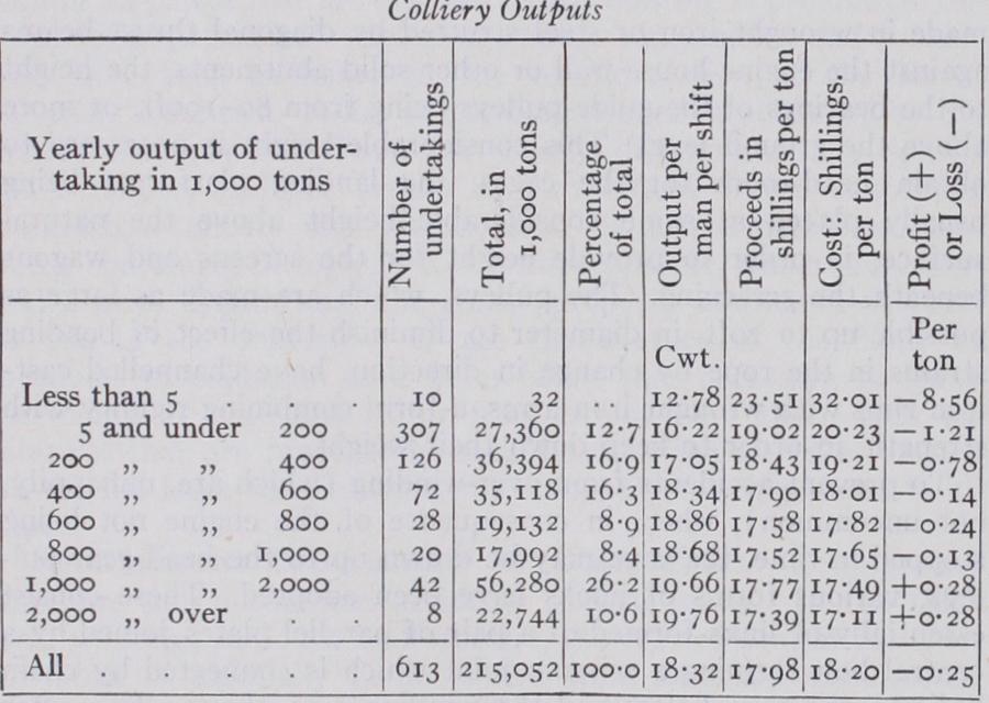
It will be seen that the figures as to cost per ton of production per man are favourable to the large as compared with the smaller concerns. (See also Section II.) Preparation of Coal for the Market—The tub when brought to the surface is passed over a weighbridge, where it is weighed by a weigher specially appointed for the purpose by the men and the owner jointly. It is then run into a "tippler," a cage turning about a horizontal axis, which discharges the load in the first half of the rotation and brings the tub back to the original position in the second, and is then run back to the pit bank to be loaded into the cage at the return journey.
The coal after being raised from the pit is subjected to a process of classification and cleaning before being despatched to the consumer. The nature and extent of these operations vary with the character of the coal, which if hard and free from shale partings may be finished by simple screening into large and nut sizes and smaller slack and "duff" ; the large being hand picked to remove the shale. But when the coal is friable and there is much small, and it is dirty owing to intermixture of shale, more elaborate sizing, and cleaning by washing, becomes necessary. Where hand-picking is done, the larger sized coal, separated by bar screens at distances of 1 -3in. apart, is spread out on a travelling band, which may be 3oof t. long and from 3-5 f t. wide, and is there carried past a line of pickers who take out and remove BY COURTESY OF MAYOR AND COULSON, LTD.
FIG. 23.-ARC WALL CHAIN CUTTER. WORKING AT 40 H.P. IT REQUIRES Fig. 23.-ARC WALL CHAIN CUTTER. WORKING AT 40 H.P. IT REQUIRES 750 CU.FT OF FREE AIR PER MINUTE the waste as it passes by, leaving the clean coal on the belt. The smaller coal passing through the screen is carried by another belt to a separate sizing plant, consisting of vibrating and/or rotating screens, to be separated into several more sizes, e.g., trebles, doubles or single nuts, unscreened small, peas and beans, and duff (dust), trebles being over 'Bin. diameter, doubles over 8in., singles over din., etc. These are cleaned by washing in either con tinuous current or pulsating (jigging) machines, where the lighter coal rises to the surface and is removed by a stream of water, while the heavier waste falls and is discharged at a lower level or at the bottom of the machine. The cleaned coal is carried to a bucket elevator and delivered to the storage bunkers ; or both water and coal may be lifted by a centrifugal pump into a large cylindrical tank, where the water drains away, leaving the coal sufficiently dry for use. Modern screening and washing plants, especially when the small coal forms a considerable pro portion of the output, are large and costly erections, requiring machinery of a capacity of 100-300 tons per hour, which absorb 350-40oh.p. In this, as in many other cases, electric motors sup plied from a central station are now preferred to separate steam engines.
Anthracite coal is sometimes broken between toothed rollers where the smaller sizes are desired, and is in all cases subjected to an elaborate system of screening before it is fit for sale. The fol lowing are the classes, sizes, values and percentages of make of the several classes of market brands of anthracite at a large modern Welsh anthracite mine in 1927.
The number and variety of coal washers is considerable; the action of all is based upon the difference in the specific gravity of the three elements entering into consideration, namely, water with a specific gravity of 1, coal with a specific gravity of about 1.3, and shale with a specific gravity of about 2.3. In some "fine coal" washing machines a bed of felspar is provided, which hav ing a specific gravity of 2.6 performs the function of a thick grating allowing of time for the particles of coal to be arrested and sent to the top. It gives a movable surface to the grating, so that every particle of the coal and shale is exposed to the action of the water.
Perhaps the most recent development in the cleaning of coal is that known as dry washing or dry cleaning. One such plant used for cleaning nuts, where the use of water would cause dis coloration of the coal and prove injurious to its marketing, is that made by the Meins Berrisford of Low Moor; the nut coal passes over an inclined glass plate which is kept clean by playing compressed air upon it. The coal passes over the glass but the dirt being heavier, falls down through a gap.
Sainte Henriette, Flenu, Belgium . 3,773 Viviers Gilly, Belgium . . . . . . . 3,75o Marcinelle No. ii. Charleroi, Belgium . . . . . Marchienne, No. 2 . 3,494 Agrappe, Mons. • 3,478 Sacre Madame, Charleroi . . . . . . . . 3,465 Ashton Moss dip workings, Lancashire . . . . . 3,36o Ronchamp No. i i pit, France . • Astley Pit, Dukinfield dip workings, Cheshire . . . . 3,15o The greatest depth attained in the Westphalian coal is at East Recklinghausen, where there are two shafts 845 metres (2,759ft.) deep.
The subject of the limiting depth of working has been very fully studied in Belgium by Prof. Simon Stassart of Mons ("Les Conditions d'exploitation a grande profondeur en Belgique," Bulletin de la Societe de l'Industrie minerale, 3 ser., vol. xiv.) who finds that no special difficulty has been met with in workings above i,ioo metres deep from increased temperature or atmos pheric pressure. The extreme temperatures in the working faces at 1,150 metres were 79° and 86° F, and the maximum in the end of a drift, i oo° ; and these were quite bearable on account of the energetic ventilation maintained and the dryness of the air. The yield per man on the working faces was 4.5 tons, and for the whole of the working force underground, 0.846 ton, which is not less than that realized in shallower mines. From the experience of such workings, it is considered that 1,50o metres would be a possible workable depth, the rock temperature being 132', and those of the intake and return galleries, 92° and io8° F respec tively. Under such conditions work would be practically im possible except with very energetic ventilation and dry air.
The grantee of a "gale" makes a certain payment to the Crown and the whole area of the grant is within the control of the presi dent of the Board of Agriculture. As a matter of fact, the free miners or "galees" in the majority of cases, sell their rights to the companies who work the coal, the others receive a royalty. This is an interesting case of workmen royalty owners.