
CONVEYORS IN MASS PRODUCTION of manufac tured articles of different kinds were used in non-mechanical industries long before the development of modern manufacturing made it profitable to consider their use. An indication of their age may be had from a book on millwrighting, published in Philadelphia by Oliver Evans in 1807 which shows the use of bucket, belt and screw conveyors in flour or grist mills. Whether these were in actual use or, like devices shown in some of Leonardo da Vinci's works, existed only in the mind of the author, it is impossible to say. Foundries were among the first of modern industries to adopt conveyors extensively, for the handling of materials on a large scale. Belts were used for car rying moulding sand for storing, for mixing or tempering, and for removing the sand from moulds. Moving platforms were also used at an early date for carrying moulds past the cupolas or pouring ladles, pausing long enough to have the metal poured and then continuing their travel until the moulds were cool enough to be dumped. This dumping in some cases, occurred while the metal casting was still very hot. Conveyors have been developed along many lines to meet the requirements of many industries. The best early example, and the one that probably gave the use of conveyors its greatest impetus, was in the High land Park plant of the Ford Motor Company in Detroit, Mich. (see MASS PRODUCTION). From a small beginning in one depart ment this grew to enormous proportions, and contained many varieties of conveyors, devised or adapted to suit the peculiar requirements of the work in this plant. This development, begin ning in about 1912 or 1913 has grown into use in practically every automobile plant, regardless of the size or quality of car built, and is now a standard part of factory equipment in any sort of manufacturing where the quantity handled is sufficient to justify it. The principle kept in mind in introducing conveyors at the Ford plant has been "to keep material three feet from the floor, and moving." The proper distance from the floor depends, of course, on the size and weight of the work and the convenience of the operator. One of the chief objects of the conveyor is to relieve the operators of as much manual labour as possible and so enable more and better work to be done. Keeping the work moving prevents the piling up of work in any department, avoids congestion around machines and aids in securing a steady flow of work by acting as a pacemaker to the men. This helps to secure a more constant output and at a higher rate than seems possible by the old method.
Conveyors are made in many forms and are adapted for use for widely diversified purposes. They may be gravity slides, rollers, either level or inclined enough to allow the work (either in single units or in some sort of container), to travel by gra vity toward the next station. Power driven chains or belts, with cleats, hooks or other devices, carry raw materials, semi-finished or completed, from machine to machine, from department to department, from machine to inspection or to sub-assembly, and from there to the final assembly. The final assembly itself is frequently done on some sort of a chain, belt or truck that is power driven at a predetermined speed. Much ingenuity is dis played in devising special forms of conveying mechanisms by which the material being carried can be automatically diverted from one line to another, or be shunted to a side track to await removal. Conveyors move material, either by power or with a minimum of human effort, supply operators with material to work upon, and carry it away after the operations are completed. One of the advantages of conveyors is the reduction of the amount of material in process, since there is no accumulation of work or material in large quantities. This greatly reduces the amount of capital invested in material. The constant flow of material, coupled with the smaller quantities in process, also enables the output to be varied to meet sales requirements, as the work can be made to flow through at varying rates of speed.
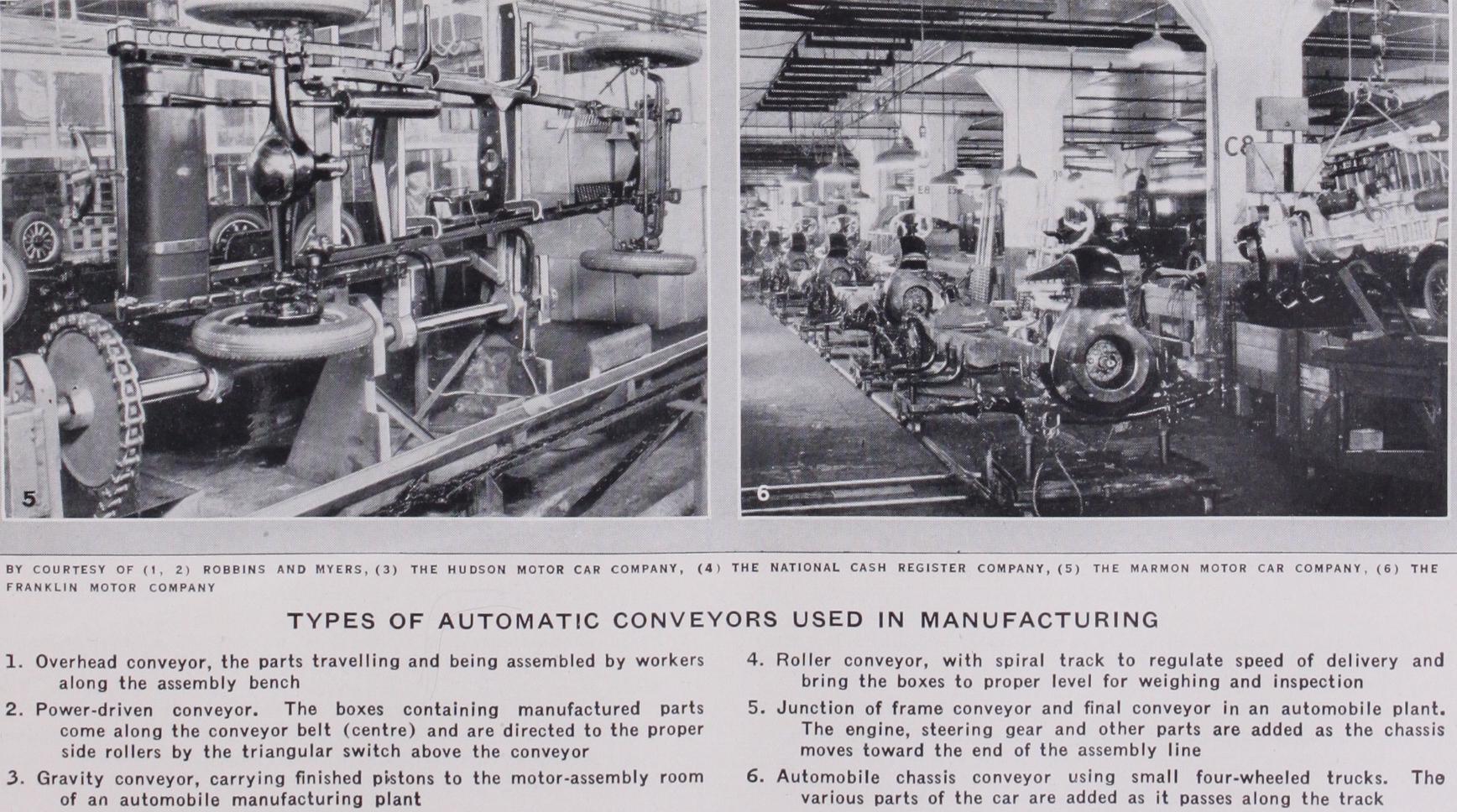
Each type or system of conveying should have individual study, the best solution being largely influenced by the results of experience gained in previous installations. The main con siderations are the convenience of the operator, keeping the con veyor and its load out of the way of operators and of the ma chines and benches. For work that is light in weight and is easily handled, the overhead conveyor is very convenient and is frequently employed in various forms. Such a conveyor is usually supported by wheels on each side of a suspended I-beam and has flat links with vertical pins so as to turn short corners. Joints must also be loose enough to permit an upward or downward movement. A typical overhead conveyor for handling fans is shown in plate I., fig. I. It is over the assembly benches and the fan parts are hung on hooks within easy reach of the operator. The worker reaches up and picks off the part he needs. When the fan is completed it is placed on a belt conveyor in the centre of the bench. From here it goes to the waist high con veyor shown in the foreground at the left. This is a slow moving conveyor and is wired with electric current so that the fans can receive a running test of the desired duration before reach ing the other end of their travel. The conveyor is wired for two kinds of current so that both types of fans can be tested at the same time. A notable feature of this conveyor combina tion is the compactness and the way in which it conserves space. It is interesting to note that the introduction of conveyors throughout a plant makes it frequently unnecessary to enlarge the factory to meet the needs of increased demands. This is possible both because of the saving in space and also because of the speeding up of production, through material being in front of the operators when needed. The waist high type of conveyor is probably used more than any other type, because of the con venience with which work can be handled from it and to it. When used in the production line it is frequently of the plain roller type and is not power driven. It is either set on a slight incline so that the work will move slowly from one machine to the next, or is level and a slight effort pushes the work along on the rollers. Conveyors of this type are usually behind the opera tor where the work is light enough to be easily handled. When however the pieces are heavy enough to be fatiguing, the con veyors run directly between the machines, where the operator has no lifting. He simply pushes the work over the rollers into the fixture on the machine. In some cases the rollers drop out of the way, in others the work is raised on locating points, but in most cases it simply slides on to the table of the machine and is located in various ways. After the operation is performed the work is restored to the production line and it proceeds to the next ma chine. In some cases spurs, or side tracks, are provided for taking work that requires a few extra operators. In other plants the conveyor line carries the work past the inspector's bench. After inspection it goes to the assembly line, is returned for salvage, or scrapped. The roller type conveyor probably finds wider application than any other. It is the least expensive to install, and operating and maintenance costs are very low. It can be used in plants with small output and it also has an im portant place in large plants, in connection with the various types of power driven conveyors that have become so much a part of modern manufacturing. An example of the utility of the roller conveyor in large or small plants is the case where a boxed article to be shipped comes down a line and is carried into the freight car where another short piece of roller conveyor, at right angles, carries it to the end of the car for stacking. These rollers can be moved without difficulty and aid greatly in loading easily and rapidly. Adaptations of this method are used in both large and small plants.
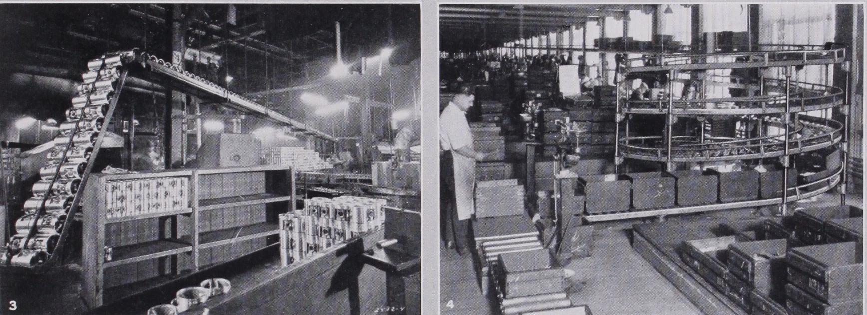
Another method of using a belt conveyor for small parts is where boxes are placed on the belt and the proper parts are placed in the boxes as they move along in front of the assemblers who pick the necessary parts from the small bins in front of the belt line. In a combination of belt and chain conveyor, the belt, made up of wooden slats, carries such large pieces as cylinder blocks, transmission housings and manifolds from one shop to another, while the chain conveyor carries smaller parts than can be placed on hooks or carriers. In one installation they are carried between two buildings and require no handling except to put them on and take them off the conveyors. An excellent example of the use of gravity in handling finished work from the piston depart ment in an automobile manufacturing plant is seen in plate I., fig. 3. After inspection the pistons are placed in the trough at the left, and, when this is filled, it is raised so as to let the pistons roll down the long inclined way to the line where the motors are being assembled. Conveyors now form a part of some types of machines. A case is found in an automobile plant where a standard washing machine is used for cleaning castings and metal parts from the oil and dirt which accumulates during the machining processes. The cylinder block in this case is placed on the conveyor and is fed slowly through the washing machine where jets of hot cleaning compound play on it from various nozzles. The speed of the conveyor is so timed that the cylinder block will be thoroughly cleaned when it reaches the other end of the machine. A somewhat similar application of the conveyor is in heat treating apparatus where the work to be treated passes through the furnace at a predetermined rate that gives it just the desired time in the furnace. With oil, gas or electric heat and pyrometer control of the heat, the use of conveyors give a much more uniform product than can possibly be secured by dependence on human observation and skill.
Roller Conveyors.—There are of course places where for one reason or another the work cannot well flow through at an absolutely uniform rate. Such a case might be where one man performed several different kinds of operations such as weighing and checking material as in plate I., fig. 4. Here the work comes in boxes from the other end of the building by a gravity roller con veyor, ending in a rather small radius spiral that delivers the boxes to the weigher at almost the floor level. This type of short radius spiral slows down the movement of the boxes due to the friction of the sides against the guard rail. This movement allows quite a number of boxes to accumulate until the weigher is ready to handle them. The boxes are delivered between two scales, the conveyors on each side taking the boxes away from the scales in either direction, as desired. The boxes are delivered to the metal platform, slid on to either scale, weighed, and sent on their way. It will be noted that the nearest scale has rollers on the platform to aid in handling the boxes. There is also a tote box storage near the spiral where boxes of material are held for inspection. An installation of this kind is very flexible and can be used to advantage in shops that are comparatively small in size. A modification of the roller conveyor in the direct product line has also been adopted in some fields. Instead of rollers to form the track, two tubes act as rails and guide and support the work fixture under the machine as well as allow it to pass to the next operation without delay. There are many applications of this type of conveyor work fixtures which allows the work to remain in the same fixture but to be worked on by different machines in the production line. In this particular case the first machine drills all the holes in the top of the crank case and the second machine all of the holes in the bottom, without disturbing the work itself. Although a power conveyor could be used and so timed as to move intermittently between the drill ings, it is not often practicable to do so. There are probably few cases where manual movement cannot be used to better advan tage in work of this kind.

Positively driven conveyors are probably more used in assem bling work than in the departments where the machining oper ations are performed. While in some cases the work is removed from the conveyor, this does not often fit in with the plan of the power driven idea, the purpose being to time the operations and to constantly urge a uniformly fast speed. It must not be for gotten however that while the power driven conveyor speeds up the slower operators it also slows down the very rapid workers, bringing them all to the greatest uniform speed that can be economically maintained. In spite of the necessary slowing down of the few extra fast workers however, the net gain is usually well worth while by increasing the speed of the great majority con cerned.
Planning Installations.—It takes very careful planning and observation to determine the best speed and so to divide the work that each operator will have time to perform his or her operations satisfactorily, without either wasting time or hurrying the operators to the point of unprofitable nerve tension. After a little experience in a properly timed line however the average operator rather prefers to have his pace set for him, and the added earnings compensate for any sentimental objection that may be held. Farm machinery, electric refrigerators, carpet sweepers, cash registers and automobiles of all types are now assembled by the use of conveyors, usually power driven. Work of the highest grade can be secured in this manner by utilizing trained men and driving the conveyor at the proper speed. After as sembling, many types of products are tested, painted, crated and deposited on the shipping platform without ever stopping. Nor is distance any longer a barrier. In one automobile plant a con veyor carries the completed engine a mile and a half, part of the way over the top of a large building, to meet the chassis on the assembly line. In another shop the building devoted to bodies contain's over eight miles of conveyors handling the various parts and finally passing the completed body through the painting booths. Among the problems to be considered in installing mov ing conveyors are those of speed and flexibility. It is not possible to rely on maximum production at all times and the successful conveyor system must function satisfactorily when only half the maximum output is required. Conveyor assembly necessitates the division of the work into single operations, sometimes to the extent of putting in a single screw, in order to tie-up, or syn chronize with the other operations that must be performed. Then when business falls off, one operator can do two or more opera tions and so keep the conveyors going at a portion of their ca pacity. In some cases of decreased production the men move with the conveyor through two or more stations. In other in stances operators stop the conveyor periodically so that each man can handle two or more operations from the single station. Some of the largest users of this method claim greater flexibility than can be secured in any other way. They can increase or de crease the output at very short notice by changing the spacing of the men, the way in which they handle the operations, and by the speed of the conveyor.
When considering conveyors as an aid to production it must be remembered that the great consideration is the number of completed units or mechanisms per hour or per day that will pass inspection. Speed in one department or by a single opera tor does not necessarily aid final production of completed ma chines. Nothing is gained by piling up a surplus of certain parts if the rest of the mechanism lags behind. The surplus simply ties up both labour and material and reduces the turnover of capital. Exceptionally rapid operators are of little direct value on actual production except as spur to raising the average or unless they can be used as instructors for the same purpose. Increased output comes from raising the efficiency of the average operator and the power driven conveyor helps by holding them to the speed that experience shows to be practical, without undue fatigue. Too high speed means fatigue and poorer work and the percentage of spoiled work goes up. It is much more economical to run the conveyors a little more slowly and get perfect work than to increase the output i o% and have a 5% spoilage. So it is necessary to study the speed of power driven conveyors very carefully in order to secure the maximum output consistent with true economy, which must consider the quality of work and must not impose undue fatigue on the operators. Some classes of work make it advisable to have the conveyor movement automatically intermittent, moving a given space and stopping for a sufficient period to have the necessary work per formed at that station. In other places the conveyor movement is manually controlled, usually by push button electric switch and varies according to the time required by the work in hand. This method is not at all common except in trying out the time at which to set the intermittent movement, or even the contin uous movement.
Intermittently Moving Conveyors.—Perhaps the best ex ample of intermittently moved conveyors in mass production work is the great specially built automobile frame making plant in Milwaukee, Wis. The cut sheets or strips that form the side rails of the frames come in from the side on a special conveyor that runs across the end of the main conveyor system. These strips are held under suitable dies and the "kink" or offset in the side frame is made to give the desired drop in the frame. After the strip is kinked the conveyor is so designed that it turns every second piece over on the other side so as to make pairs, or rights and lefts, before they reach the large presses that form these strips into channels with the proper offset and so complete the side rails. These side rails, in pairs of rights and lefts, now start down the great central conveyor, one on each side, stopping every i8 ft. Here previously formed cross members are fed in from the side and are put in place by operators. Special riveting machines held on long, pivoted arms, swing in from each side and rivet the cross members in place, withdrawing while the conveyor moves another 18 ft. and takes the first frame to the next position while a new frame has come into position for welding in the first cross member. At each station more parts are put into place and riveted either automatically or semi-auto matically. Spring horns or supports, step brackets and other parts are fed to the central conveyor and attached to the frame at the proper point. When the conveyor has carried the frame to the other end it is complete and ready to be transferred to another conveyor that carries it into another building where it is automatically painted. The painting conveyor first carries the frame through a washing tank to remove all grease, of ter which it is dried before going into the paint tanks where the painting proper is done. From the paint tanks the frames go by devious routes to the storage racks where they dry. This is as high as a four or five storey building and can hold thousands of completed frames while they are awaiting shipment. Conveyors also carry them from the storage racks to the shipping platform, and to the cars that carry them away. The actuating mechanism of this huge intermittent conveying system is a very large Geneva stop motion, so designed and timed as to move the conveyor 18 ft.
and pause for a specific number of seconds while the various operations are performed. Although other mechanisms, such as interrupted gears or various linkages can be used to secure the same result, the Geneva stop motion has much to commend it for work of this kind.
Some idea of the engineering problem presented in designing this plant can be had from the rather startling fact that it was necessary to synchronize 552 operations in making the average automobile frame. These operations, when performed on a day's production of 7 ,000 frames at the rate of 36o frames per hour, aggregate about 4,000,000 operations in the day's production. And yet, in spite of the necessary complications in such a plant, a force of zoo men can change the plant over for the production of an entirely different frame, in ten hours. An interesting de velopment or modification in conveyor mechanism handling motor cars in a plant in Indianapolis, Ind. is shown in plate I., fig. 5 which shows the junction of the frame conveyor at the left and of the final conveyor where the cars are completed. The frames are turned upside down on the first conveyor and both the front and rear axles bolted in place, as well as the fuel tank, the step brackets and a few minor parts. The wheels are also mounted before the chassis reaches the end of the line at the left. At this point the frame pauses over a pair of substantial arms provided with the hooks A and B. C and D the arms being seen at E and H. These hooks swing up over the side frames and clamp them to the arms. Then suitable mechanism actuates the chain at the left and the arms swing over until the chassis is right side up and the wheels in the V shaped tracks shown in the foreground. As shown the frame is half way over, being held securely by the four clamps previously mentioned. When the chassis is deposited right side up in the assembly track the four clamps release auto matically and the arms swing back ready for the next chassis. The final assembly is driven by the chain seen between the tracks and just beyond this point, the engine comes out of the test room on an overhead carrier and is lowered into the front end of the chassis. The steering mechanism, body, etc. all feed into the assembly line within a short space.
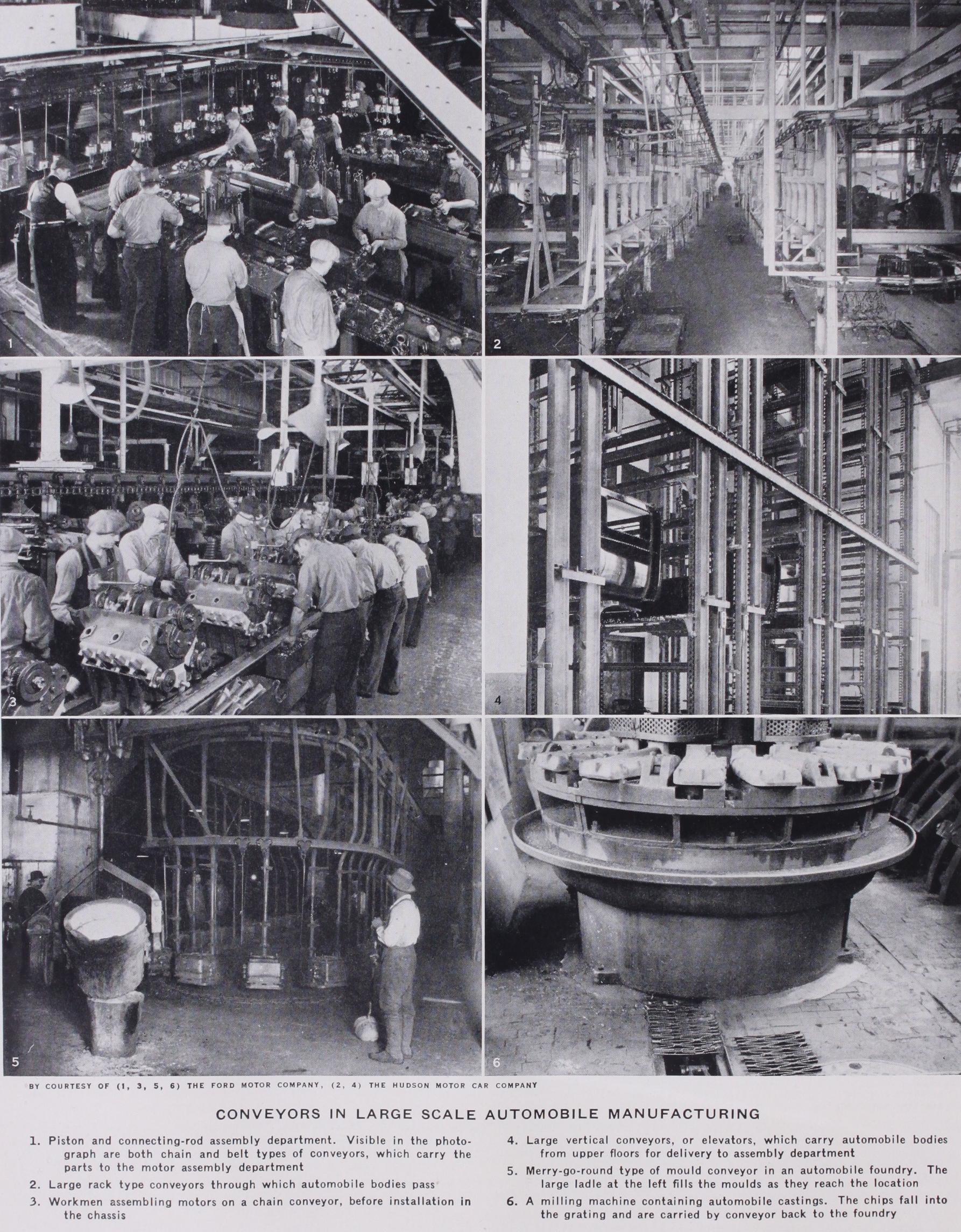
An entirely different type of assembly line is seen in plate I., fig. 6. Here each end of the chassis is carried by a light four wheel truck. These trucks are moved from the chain shown be tween the tracks, these tracks being channels sunk in the floor to guide the wheels of the trucks. A short double conveyor for handling fenders is of the slat type. Slats with blocks support the fenders while they are being assembled to their running boards. Each belt has its own motor ; the motion is reduced by gears from the motor to variable speed pulleys and further reduced by a worm gear speed reducer, a chain from this driving the conveyor, whose speed can be varied by adjustable cone pul leys. Two motor lines, one empty so as to show the chain and carriers, can also be used. Small trucks or carriers are fastened to the chain, the front truck having a trough to accommodate two different wheelbases. Steel racks containing small parts for the assembler are at convenient positions beside the track. Over the end of this line is a large opening in the floor through which the chassis is lifted to the second floor as in plate II., fig. 1. These also shows the chassis assembly lines on the floor below. The two hoist operators control the monorail hoists which lift the chassis to the upper tracks and also handle the bodies over the chassis after it is in line. The bodies come in from an opening in the side, not shown in the illustration. These hoists are usually operated by girls, who become very expert.
Conveyors also play an important part in the construction of the bodies themselves. A general view down one of the aisles of a body plant is given in plate II., fig. 2. This building is approxi mately i,000 ft. long and perhaps 40o ft. wide and contains 81 m. of conveyors. A view of the line where the bodies approach com pletion can be had in plate II., fig. 3. Here the bodies are on low trucks, the doors are hung, and they are nearly complete except for the roof. The seat cushions come from their special depart ment on the conveyors shown and can be picked off and put into place with a minimum of effort. In another way of handling the bodies as they approach completion, trucks hold the bodies at the most convenient height for the final operations, but the trucks also fold down so that they can be used in the low position if desired. At the end of the building is a huge vertical conveyor plate II., fig. 4, which carries the bodies in an almost continuous stream, from the finished floor to the great body motor trailers that carry them to the shop where they are put on the chassis. Just outside the vertical conveyor is the body trailer, holding 16 bodies, on the low roller trucks that enable them to be rolled into place easily and quickly. Then the small tractor hauls them to the other plant.
An interesting conveyor application is shown in plate II., fig. 5. The first is in the foundry of an automobile plant and is known as the merry-go-round, where the moulds are carried past the touring station, although, being small castings, the ladles of molten metal can be carried to any of the moulds. The metal comes to this con veyor in large ladles so as to reduce the labour of carrying to the minimum. After the castings reach the machine shop the chips, which accumulate rapidly in these days of modern machining, must be disposed of. To reduce labour and to keep the chips off the floor and out of the way, they are returned to the foundry without human labour by the conveyor in plate II., fig. 6. Running under the shop floor at convenient intervals, are chain conveyors with drags or scoops that carry the chips with them. Above the chain is a narrow opening covered by grating, part of which has been removed to show the conveyor chain beneath. This carries the chips direct to the foundry and is not only a convenience but a great time saver.
Both expansion and construction must be considered in planning a conveyor line, and great care and experience are required to get the best results from a given amount of floor space. Instead of using straight line conveyors it is frequently found advisable to curve the conveyor line and even to let it double on itself. Some times this doubling on itself occurs two or three times and may bring the finishing point rather near the beginning. In such a case the parts in question would probably be made or assembled in a department at right angles to the main conveyor line. This dou bling, or sinuous conveyor line frequently lends itself to expansion more readily than the straight line conveyor. Where the depart ment provides sufficient room for expansion, as is nearly always necessary, it has often been found more desirable to lay out a sinuous conveyor that doubles on itself before reaching the end of the department. With such a lay-out additional workers can be put on the conveyor line by extending one of the "loops," follow ing this with other and similar extensions as occasion demands. One great advantage of this method is that, regardless of the ex pansion made in the department, the relation to the main con veyor line is not disturbed. The material continues to enter and leave the department at the same point until the room provided for the department is entirely outgrown. (See MECHANICAL