
CRANES, machines by means of which heavy bodies may be lifted, and also displaced horizontally, within certain defined limits (so called from the resemblance to the long neck of the bird, cf. Gr. 7Epavos, Fr. grue). Strictly speaking, the name alludes to the arm or jib from which the load to be moved is suspended, but it is now used in a wider sense to include the whole mechan ism by which a load is raised vertically and moved horizontally. Machines used for lifting only are not called cranes, but winches, lifts or hoists, while the term elevator or conveyor is commonly given to appliances which continuously, not in separate loads, move materials like grain or coal in a vertical, horizontal or diagonal direction. (See CONVEYORS.) The use of cranes is of great antiquity, but it is only since the great industrial develop ment of the i 9th century, and the introduction of other motive powers than hand labour, that the crane has acquired the im portant and indispensable position it now occupies. In all places where finished goods are handled, or manufactured goods are made, cranes of various forms are in universal use.
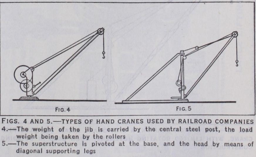
The different kinds of motive power used to actuate cranes— manual, steam, hydraulic, electric—give a further classification. Hand cranes are extremely useful where the load is not exces sive and the quantities to be dealt with are not great, also where speed is not important and first cost is an essential consideration. The net effective work of lifting that can be performed by a man turning a handle may be taken, for intermittent work, as being on an average about 5,00o ft.-lb. per minute; this is equivalent to one ton lifted about 2 4f t. per minute, so that four men can by a crane raise one ton 9ft. in a minute or nine tons i f t. per minute. It is at once evident that hand power is only suitable for cranes of moderate power, or in cases where heavy loads have to be lifted only very occasionally. This point is dwelt upon because the speed limitations of the hand-crane are often overlooked by engineers. Steam is an extremely useful motive power for all cranes that are not worked off a central power station. The steam crane has the immense advantage of being completely self-con tained. It can be moved (by its own locomotive power if desired) long distances without requiring any complicated means of con veying power to it ; and it is rapid in work, fairly economical and can be adapted to the most varying circumstances. Where, how ever, there are a number of cranes all belonging to the same installation, and these are placed so as to be conveniently worked from a central power station, and where the work is rapid, heavy and continuous, as is the case at large ports, docks and railway or other warehouses, experience has shown that it is best to pro duce the power in a generating station and distribute it to the cranes. Down to the closing decades of the i9th century hydrau lic power was practically the only system available for working cranes from a power station. The hydraulic crane is rapid in action, very smooth and silent in working, easy to handle and not excessive in cost or upkeep—advantages which have secured its adoption in every part of the world. Electricity as a motive power for cranes is of more recent introduction. The electric transmission of energy can be performed with an efficiency not reached by any other method, and the electric motor readily adapts itself to cranes. When they are worked from a power station the great advantage is gained that the same plant which drives them can be used for many other purposes, such as work ing machine tools and supplying current for lighting. For dock side jib cranes the use of electric power is making rapid strides. For overhead travellers in workshops, and for most of the cranes which fall into our second class, electricity as a motive power has already displaced nearly every other method. Cranes driven by shafting, or by mechanical power, have been largely super seded by electric cranes, principally on account of the much greater economy of transmission. For many years the best work shop travellers were those driven by quick running ropes ; these performed admirable service, but they have given place to the more modern electric traveller.

When the loads are heavy the above mechanisms are supple mented by systems of purchase blocks suspended from the jib or the traveller crab ; and in barrel cranes trains of rotating gear ing are interposed between the motor, or manual bar, and the barrel (fig. 3).
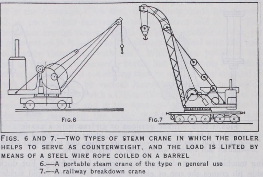
In both of these types the motions provided for are those of hoisting the load, slewing or revolving the superstructure about a perpendicular axis through the centre of the truck, travelling the crane along the line, and lifting and lowering the jib. This latter motion is known as derricking or lulling. The boiler is mounted on the tail girders at the back of the revolving super structure. In this position it acts as a counterweight, which, together with cast-iron ballast underneath, serves to balance off the forward moment of the load and jib. Two cylinders are mounted one on either side of the crane. These may be either vertical, horizontal or inclined. They drive direct on to a trans verse horizontal shaft from which the various motions are taken. The lifting mechanism is of the type illustrated (fig. 3), and is operated by a pinion which slides on its shaft so that the load can be lowered, under control of a band brake on the barrel, with out revolving the engine shaft. The crane revolves on rollers carried on pins fixed to the bed of the revolving superstructure. A circular path for these rollers is fixed to the top of the truck. For large cranes a live ring of rollers is often used. This con sists of a number of rollers the pins of which are all carried by either one or two rings. Thus the live ring revolves on the truck at half the rate of revolution of the superstructure. The live ring is thus a large roller thrust bear ing and makes the slewing very free besides giving a good distri bution of load. A circular steel curb ring fitted with teeth is mounted on the top of the truck, the teeth of which engage with a vertical pinion mounted on a shaft which is carried by the superstructure. This shaft is re volved through a train of spur gearing by friction cones which are keyed to the engine shaft and drive down through bevel gears.
The motions of travelling and derricking are also taken from the engine shaft, the former being operated by a vertical shaft which passes down into the truck through the middle of the centre post or pin about which the crane revolves. From there the motion is taken on to the axles through bevel gear and longitu dinal shafts. The jib is supported by a rope or ropes which pass over sheaves at the top of the superstructure, and are coiled on the derricking barrel. The latter is driven from the engine shaft, usually through a worm and wheel which are made so that the motion will not reverse under the weight of the jib and load. This is done for safety so that the derricking clutch can be with drawn without allowing the jib to run out.
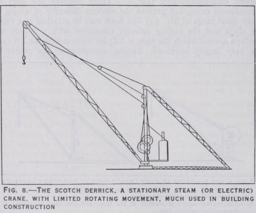
Another familiar form of steam crane, and one much used for building construction, is the Scotch derrick (fig. 8). It oper ates much as described above, except that it does not travel, and can only slew through part of a circle. It is often mounted on steel framed towers so as to get extra height of lift. Scotch der ricks are also often operated by electric motors.
Hydraulic Cranes.—A common type of hydraulic crane is illustrated in fig. 9. The load is lifted by means of a ram (fig. 2). Similar rams are mounted horizontally at the top of the or non-revolving portion of the crane. These rams pull on chains which are wrapped round the revolving mast and give the crane the motion of slewing. A further ram is mounted on the back of the superstructure and is used to luff the jib in and out. Hydraulic cranes are usually travelled by hand power, but sometimes re volving hydraulic engines are fitted for this purpose.
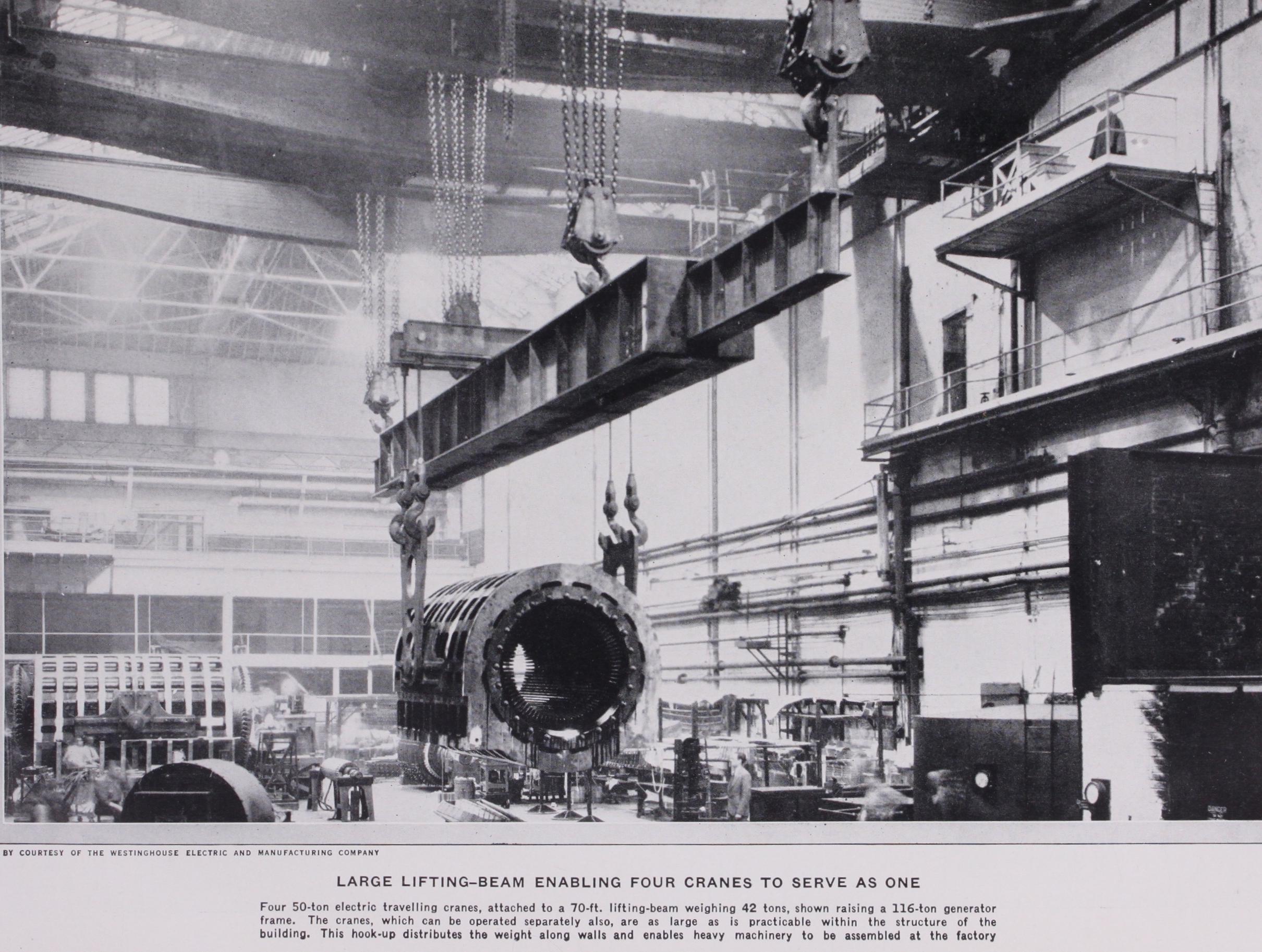
Electric Cranes.—The two types of electric cranes most gen erally used are those shown in figs. i o and r t . The former shows the common type of overhead traveller. It consists of two main or bridge girders the ends of which are attached to end carriages which travel on the longitudinal gantry girders or runway. The main girders may be of the single joist construction for small cranes, or lattice or plate girders for large cranes. The hoisting winch is carried on a frame mounted on wheels called the crab or jenny. This crab moves on either the top or bottom booms of the main girders and carries a separate motor for this motion of "cross traversing." The controllers for all these tions are in the driver's cage at one or other end of the main ers. Sometimes a revolving jib crane is mounted on the jenny (fig. 12) . Such a type is useful where it is required to pick up loads outside the shop runway rails, but it has the disadvantage of taking up valuable headroom.
Allowance must be made in designing the gantry girders for the eccentric load.
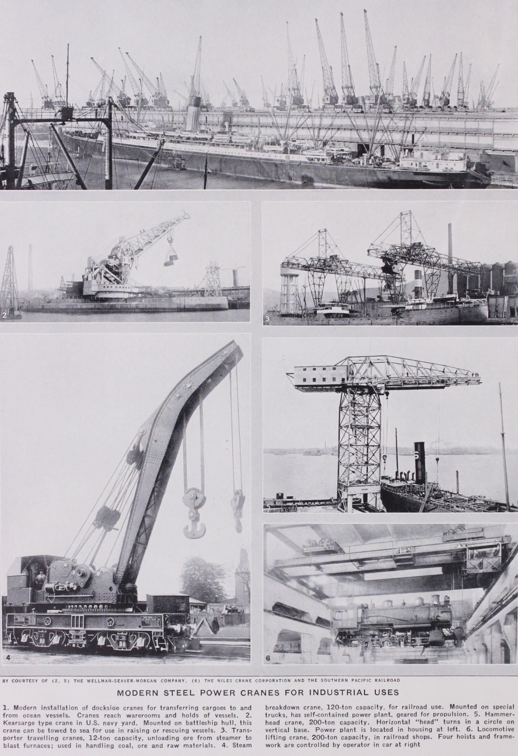
Dockside cranes (fig. r I) are a very important class. They are usually of the revolving type, and are either mounted on the roof of the warehouse or on a gantry on the quay. This latter may be of the half portal type as illustrated, or the full portal type where both crane rails are on the quay. They have four motions, that of lifting the load, slewing, luffing or derricking the jib, and travelling along the quay or .roof. They vary in capacity from i 2 to 5 tons, which are handled at a radius of from 25 to 9oft.
Fig. 13 shows a useful type of steam crane for reclaiming coal from a store at a power sta tion. It is mounted on a cater pillar truck, and operates a grab. The latter picks up 2 4 tons of coal per lift and weighs, empty, 2 a tons. The boiler has a steam ing capacity of 1,400lb. per hour, and the crane will handle coal at the rate of 600 tons per hour without losing steam. For this purpose a steam crane has the advantage of mobility, but is handicapped by its output being limited by its boiler capacity. The whole crane with ballast and load weighs S9 tons, and has a maximum track pressure of 2.3 tons per square foot with the jib across the corner of one track.
Fig. 14 shows an electric crane for discharging coal from ships by means of a grab. The coal is deposited into a hopper in front of the gantry, from whence it passes through a weighing machine and on to a belt conveyor. The latter discharges the coal through the rear of the gantry on to another conveyor, not shown in the fig., into the boiler house bunkers. It will be noted that the motions most used are those of lifting and luffing.
Fig. 15 shows another method of carrying out a similar duty by means of an electric transporter crane. Here the front apron girder or boom is hinged at the rear end to allow ships to be brought in. The boom is thus lowered out over the hatch, and the trolley moves backwards and forwards on it. The trolley carries the lifting and cross traversing machinery and the driver's cabin. The lifting machinery revolves on a large ball race, and carries a jib from the end of which the grab is suspended. This machine was designed to give a rate of discharge of 15o tons per hour through the ship. It is important in unloading bulk cargo to make sufficient allowance for the time lost in cleaning up nearly empty hatches and in shifting to new hatches. In this transporter the rate of discharge with a fairly full hatch was 23o tons per hour, but the average rate throughout a ship holding 2,70o tons of coal was i 6o tons per hour.

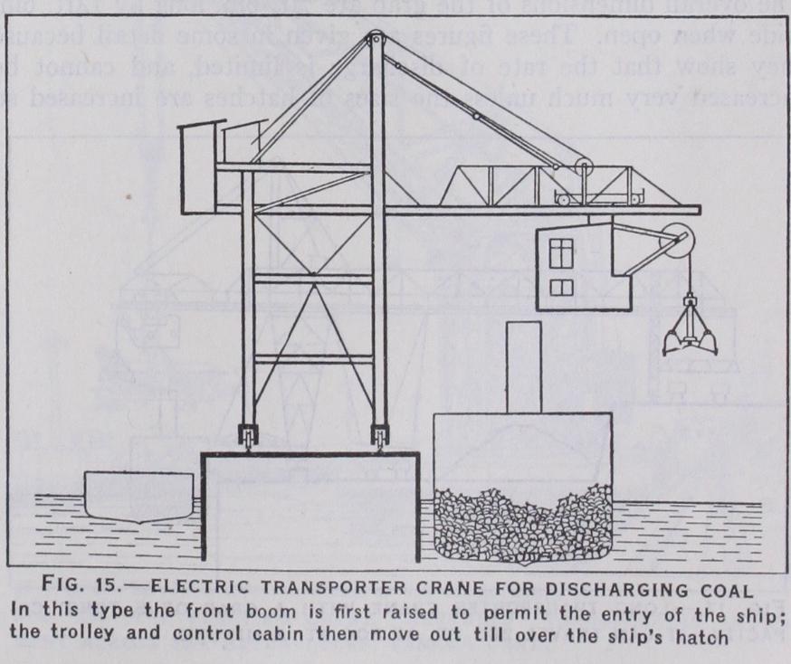
Fig. 16 shows a similar machine for unloading iron ore. It has a capacity of 30o tons per hour without making the allow ances mentioned above. The gross weight of grab and contents is 18 to 19 tons, according to the class of ore handled. There are two hoisting motors and two winches, one for closing the grab or digging, and the other for holding the head of the grab while discharging. Each motor has a capacity of 155 b.h.p. on a one hour rating, and 200 b.h.p. on a half-hour rating. After the grab has been filled both winches lift together. The crane can also be used for handling loaded 2o-ton wagons. The whole of the hoisting gear revolves on a circular roller path, and the ropes are led direct from the barrels to the grab, no jib being used as in fig. 13. This arrangement allows the grab to be turned by means of slewing gear in the crab, so as to pick up the ore at the most suitable angle. The speed of lifting is 2 2of t. per minute, cross traverse of crab 3ooft. per minute with two 4o h.p.motors, slewing three revolutions per minute with one 12 h.p. motor, travelling along the quay 4oft. per minute with a 4o h.p. motor. The overall dimensions of the grab are 7 f t. 6in. long by 14f t. 6in. wide when open. These figures are given in some detail because they show that the rate of discharge is limited, and cannot be increased very much unless the sizes of hatches are increased so as to allow of the use of larger grabs. For the heaviest duties a transporter has some advantage over a crane, as higher speeds can be used for the cross traverse than are possible with the slewing or luffing motions of a crane, owing to the fact that the length of rope above the load is not so great and consequently the inertia of stopping and starting does not produce such a swing on the grab. It must always be remembered that control of the load is as important for quick working as the actual speed of any particular motion, and future development of this class of machinery will probably be more with the object of getting better control than of increasing either the load or the speeds. Fig. 17 shows a similar machine for unloading iron ore. The grab has a capacity of five tons, and discharges either on to the quay or into a bunker at the rear end. The crab travels a distance of 26of t. at a speed of 800ft. per minute.
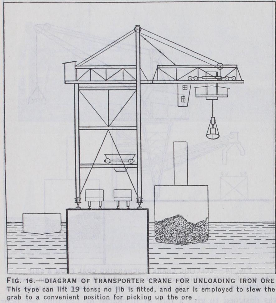
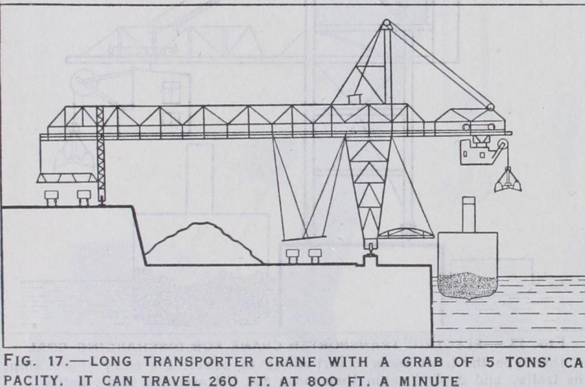
Fig. 18 shows the "hammer-headed" crane which is used for loads up to 23o tons. It is used for lifting heavy machinery, either for construction or repair, into and out of ships. The general arrangements are similar to those described above, but all the mo tions are much slower. The heavy lifting machinery is fixed at the tail of the crane, as is also the racking machinery. The jenny is pulled in and out by ropes, and only carries the sheaves over which the hoist ropes pass. Fig.
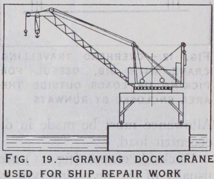
19 shows a very usual form of graving dock crane having a ca pacity of 3o tons at 83ft. radius.
It is used for ship repair work. The superstructure revolves on a live ring of rollers, and the arrangement of machinery is similar though much larger than that of the dockside cranes described above.
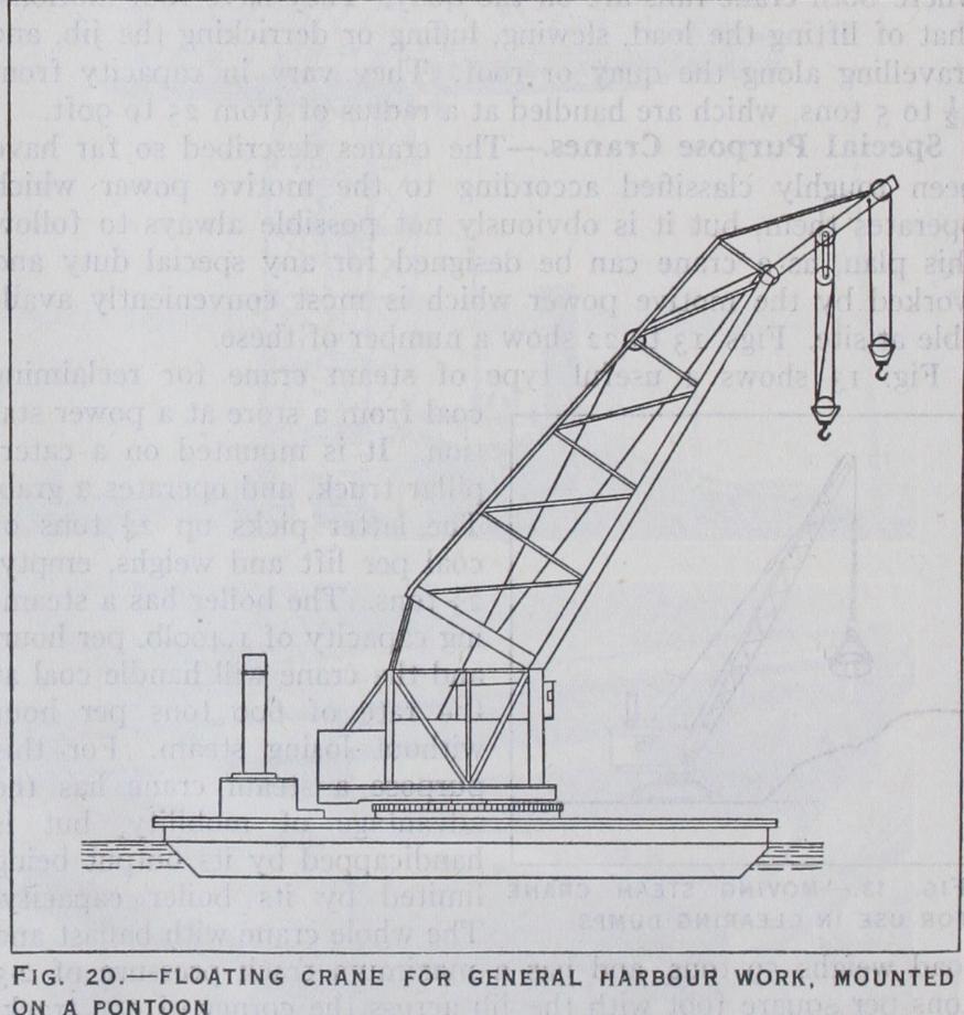
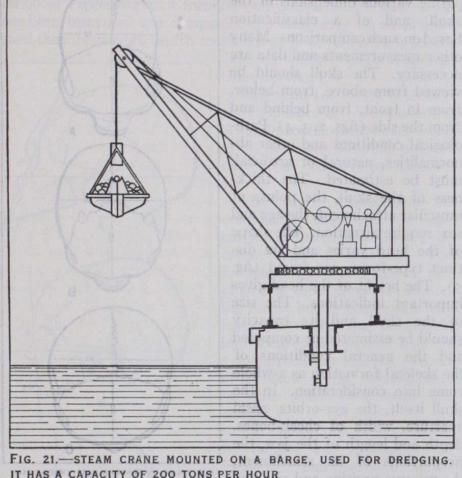
Where a graving dock is not available, and for general work in a harbour where large lifts are required at different places, it is usual to mount a crane on a large pontoon (fig. 2o). This floating crane revolves on a base fixed to the deck, and the jib is supported by screws, which enables the jib to be luffed in and out. Another type of floating crane is shown (fig. 21). Three such cranes, operated by steam, are commonly mounted on a hopper barge, one being at the bow and two at the stern. They are used for dredging, each crane having a capacity up to about 200 tons of silt per hour.
A special form of jib crane, designed to meet a particular pur pose, is the Titan (fig. 22), largely used in the construction of piers and breakwaters. It contains all the essential elements of the hammer-head crane, of which it may be considered to be the parent ; in fact, the only essential difference is that the Titan is portable, and the hammer-head crane fixed. The Titan was the first type of large portable crane in which full use was made of a truly horizontal movement of the load; for the purpose for which the type is designed, viz. , setting concrete blocks in courses, the motion is almost a necessity. A simple form of crane for lif t ing heavy loads is shown in fig. 23. This shows the shear legs.
Here the place of the jib is taken by two inclined legs joined together at the top and pivoted at the bottom ; a third back leg is connected at the top to the other two, and the bottom leg is coupled to a nut which runs, along a long horizontal screw. This movement allows the front legs to fold back over the quay so that a load can be taken out of a vessel and deposited on the quay wall. Methods of Control.—The importance of methods of con trol in the handling of bulk cargo in grabs has already been men tioned. Speed of working is, however, equally important in handling mixed cargo so that the ship can be turned round in the least possible time. The growth in the size of ships has necessi tated much longer radius cranes than were formerly used, i.e., up to about 9of t. radius instead of about 5o feet. It has been found that not much, if any, time is saved by increasing the speeds of the various motions beyond about 2 5of t. p.m. for lifting, 400f t. p.m. for lowering, 600ft.
p.m. for slewing and i 8of t. p.m.
for luffing. These speeds are higher than those commonly used.
They have, however, been ex ceeded. That rate at which a ship can be loaded or discharged can be increased by improvements in two directions; firstly, by better arrangements of the positions of the sheds and cranes relative to the quays, so that more cranes can work at one hatch at the same time without getting in each other's way, and, secondly, by improving the electrical controls so that high speeds can be utilized where a clear run for the load occurs, at the same time enabling the driver to slow down, and to creep where necessary to avoid swinging the load into the sides of hatches and other obstructions. The former is the direction in which most improvement is taking place. It may be said that the arrangement of a number of cranes situated on the roof of a quay enables several cranes to work in the same hatch. In this case the cranes work almost entirely by lifting and luffing, instead of by lifting and slewing, the cargo being worked from, or to, either the quay itself or platforms projecting from the various floors. With regard to electrical control it may be said that much has been done recently, but that the problem has by no means been solved. It is complicated by the introduction of alternating current in place of direct.
BIBLIOGRAPHY.-A. Ernst, Die Hebezeuge (1903) ; A. Bottcher, Bibliography.-A. Ernst, Die Hebezeuge (1903) ; A. Bottcher, Cranes (1908) ; C. W. Hill, Electric Crane Construction (pp') ; H. H. Broughton, Electrical Handling of Materials (1921-23) ; H. Davies, Elevating and Conveying Machinery (1922-23) ; F. E. Chilton, Electric Cranes and Hauling Machines (1923) ; H. Wilda, The Design of Cranes and Hoists (1925). (R. B. Pi.)