
DYNAMOMETER, an instrument for measuring force ex erted by men, animals and machines. (Gr. bvvapts, strength, and l2 Tpov, a measure). The name has been applied generally to all kinds of instruments used in the measurement of a force, as for example electric dynamometers, but the term specially denotes apparatus used in connection with the measurement of work, or in the measurement of the horse-power of engines and motors. If P represent the average value of the component of a force in the direction of the displacement, s, of its point of application, the product Ps measures the work done during the displacement. When the force acts on a body free to turn about a fixed axis only, it is convenient to express the work done by the trans formed product TO, where T is the average turning moment or torque acting to produce the displacement 0 radians. The ap paratus used to measure P or T is the dynamometer. The factors s or 6 are observed independently. Apparatus is added to some dynamometers by means of which a curve showing the variations of P on a distance base is drawn automatically, the area of the diagram representing the work done ; with others, integrating apparatus is combined, from which the work done during a given interval may be read off directly. It is convenient to distinguish between absorption and transmission dynamometers. In the first kind the work done is converted into heat ; in the second it is transmitted, of ter measurement, for use.
If more than one force be applied to hold the brake from turn ing, Fr. and therefore T, are measured by the algebraical sum of their individual moments with respect to the axis. If the brake is not balanced, its moment about the axis must be included. There fore, quite generally, The factor 0 of the product TO is found by means of a revolution counter. The power of a motor is measured by the rate at which it works, and this is expressed by Tw= in foot-pounds T2rN per second, or in horse-power units. The latter is com monly referred to as the "brake horse-power." The maintenance of the conditions of steadiness implied in equation (I) depends upon the constancy of F, and therefore of the coefficient of friction µ between the rubbing surfaces. The heating at the sur faces, the variations in their smoothness, and the variations of the lubrication make ,u con tinuously variable, and necessi tate frequent adjustment of W or of the nuts. J. V. Poncelet (1788-1867) invented a form of Prony brake which automatically adjusted its grip as ,u changed, thereby maintaining F constant.
The principle of the compen sating brake devised by J. G. Appold (180o-1865) is shown in fig. 1. A flexible steel band, lined with wood blocks, is gripped on the motor fly-wheel or pulley by a screw A, which, together with W, is adjusted to hold the brake steady. Compensation is effected by the lever L inserted at B.
This has a slotted end, engaged by a pin P fixed to the framing, and it will be seen that its action is to slacken the band if the load tends to rise and to tighten it in the contrary case. The external forces holding the brake from turning are W, distant R from the axis, and the reaction, say, of the lever against the fixed pin P, distant R from the axis. The moment of may be posi tive or negative. The torque T at any instant of steady running is therefore { WR± .
Lord Kelvin patented a brake in 1858 (fig. 2) consisting of a rope or cord wrapped round the circumference of a rotating wheel, to one end of which is applied a regulated force, the other end being fixed to a spring balance. The ropes are spaced laterally by the blocks B, B, B, B, which also serve to prevent them from slipping sideways. When the wheel is turning in the direction indicated, the forces holding the band still are W, and P, the observed pull on the spring balance. Both these forces usually act at the same radius R, the distance from the axis to the centre line of the rope, in which case the torque T is (W — P)R, and con sequently the brake horse-power is • When µ 33,000 changes the weight W rises or falls against the action of the spring balance until a stable condition of running is obtained. The ratio W is given by where e= 2.718; µ is the coefficient of friction P and 0 the angle, measured in radians, subtended by the arc of contact between the rope and the wheel. In fig. 2 P, 6 = 2 7r. The ratio W/P increases very rapidly as 0 is increased, and therefore, by making 0 sufficiently large, P may conveniently be made a small fraction of W, thereby rendering errors of observation of the spring balance negligible. Thus this kind of brake, though cheap to make, is, when 0 is large enough, an exceedingly accurate measuring instrument, readily applied and easily controlled.
It is sometimes necessary to use water to keep the brake wheel cool. Engines specially designed for testing are usually provided with a brake wheel having a trough-shaped rim. Water trickles continuously into the trough, and the centrifugal action holds it as an inside lining against the rim, where it slowly evaporates.
Fig. 3 shows a band-brake invented by Professor James Thomson, suitable for testing motors exerting a constant torque (see Engineering, 22nd October 188o). To maintain constant, compensation for variation of is made by inversely varying 0. A and B are fast and loose pulleys, and the brake band is placed partly over the one and partly over the other. Weights W and w are adjusted to the torque. The band turns with the fast pulley if ,u increase, thereby slightly turning the loose pulley, otherwise at rest, until 0 is adjusted to the new value of ,u. This form of brake was also invented independently by J. A. M. L. Car pentier, and the principle has been used in the Raffard brake. A self-compensating brake of another kind, by Marcel Deprez, was described with Carpentier's in 188o (Bulletin de la societe d'encouragement, Paris). W. E. Ayrton and J. Perry used a band or rope brake in which compensation is effected by the pulley drawing in or letting out a part of the band or rope which has been roughened or in which a knot has been tied.
In an effective water-brake invented by W. Froude (see Proc. Inst. M. E. 1877), two similar castings, A and B, each consisting of a boss and circumferential annular channel, are placed face to face on a shaft, to which B is keyed, A being free (fig. 4). A ring tube of elliptical section is thus formed. Each channel is divided into a series of pockets by equally spaced vanes inclined at When A is held still, and B rotated, centrifugal action sets up vortex currents in the water in the pockets; thus a continuous circulation is caused between B and A, and the consequent changes of momentum give rise to oblique reactions. The moments of the components of these actions and reactions in a plane to which the axis of rotation is at right angles are the two aspects of the torque acting, and therefore the torque acting on B through the shaft is measured by the torque required to hold A still. Froude con structed a brake to take up 2,000 H.P. at 90 revs. per min. by duplicating this apparatus. This replaced the propeller of the ship whose engines were to be tested, and the outer casing was held from turning by a suitable arrangement of levers carried to weigh ing apparatus conveniently disposed on the wharf. The torque corresponding to 2,000 H.P. at 90 revs. per min. is 116,772 foot pounds, and a brake 5 ft. in diameter gave this resistance. Thin metal sluices were arranged to slide between the wheel and casing, and by their means the range of action could be varied from 300 H.P. at 120 revs. per min. to the maximum. The form of the Froude Brake developed by Messrs. Heenan and Froude is widely used. It is specially convenient for measuring the torque of high speed engines.

Professor Osborne Reynolds in 1887 patented a water-brake (see Proc. Inst. C.E. 99, p. 167), using Froude's turbine to obtain the highly resisting spiral vortices, and arranging passages in the casing for the entry of water at the hub of the wheel and its exit at the circumference. Water enters at E (fig. 5), and finds its way into the interior of the wheel, A, driving the air in front of it through the air-passages K, K. Then following into the pocketed chambers V1, V2, it is caught into the vortex, and finally escapes at the circumference, flowing away at F. The air-ways k, k, in the fixed vanes establish communication between the cores of the vortices and the atmosphere. From to 3o H.P. may be measured at ioo revs. per min. by a brake-wheel of this kind i8 in. in diam eter. For other speeds the power varies as the cube of the speed. The casing is held from turning by weights hanging on an attached arm. The cocks regulating the water are connected to the casing, so that any tilting automatically regulates the flow, and therefore the thickness of the film in the vortex. In this way the brake may be arranged to maintain a constant torque, notwithstanding varia tion of the speed. In G. I. Alden's brake (see Trans. Amer. Soc. Eng. vol. xi.) the resistance is obtained by turning a cast iron disk against the frictional resistance of two thin copper plates, which are held in a casing free to turn upon the shaft, and are so arranged that the pressure between the rubbing surfaces is controlled, and the heat developed by friction carried away, by the regulated flow of water through the casing. The torque required to hold the casing still against the action of the disk measures the torque exerted by the shaft to which the disk is keyed.
In spring dynamometers designed to measure a transmitted torque, the mechanical problem of ascertaining the change of form of the spring is complicated by the fact that the spring and the whole apparatus are rotating together. In the Ayrton and Perry transmission dynamometer or spring coupling of this type, the relative angular displacement is proportional to the radius of the circle described by the end of a light lever operated by mechanism between the spring-connected parts. By a device used by W. E. Dalby (Proc. Inst. C.E. 1897-1898, p. 132) the change in form of the spring is shown on a fixed indicator, which may be placed in any convenient position. Two equal sprocket wheels, are fastened, the one to the spring pulley, the other to the shaft. An endless band is placed over them to form two loops, which during rotation remain at the same distance apart, unless relative angular displacement occurs between and Q2 (fig. 7) due to a change in form of the spring. The change in the distance d is proportional to the change in the torque transmitted from the shaft to the pulley. To measure this, guide pulleys are placed in the loops guided by a geometric slide, the one pulley carrying a scale, and the other an index. A recording drum or integrating apparatus may be arranged on the pulley frames.
Every part of a machine transmitting force suffers elastic defor mation, and the force may be measured indirectly by measuring the deformation. The relation between the two should in all cases be found experimentally. G. A. Hirn (see Les Pandynamometres, Paris, 1876) employed this principle to measure the torque trans mitted by a shaft. Signor Rosio used a telephonic method to effect the same end, and mechanical, optical and telephonic devices have been utilized by the Rev. F. J. Jervis Smith. (See Phil. Mag. February 1898.) H. Frahm (Zeitschri f t des V ereins deutscher, Ingenieure, 31st May 1902), during an important investigation on the torsional vibration of propeller shafts, measured the relative angular displacement of two flanges on a propeller shaft, selected as far apart as possible, by means of an electrical device (Engineering, 6th of Feb ruary 1903). These measurements were utilized in combination with appropriate elastic coefficients of the material to find the horse-power transmitted from the en gines along the shaft to the propeller. In this way the effective horse-power and also the mechanical effici ency of a number of large marine engines, each of several thousand horse-power, have been determined.
The method of deducing the power transmitted from observa tions based on the elastic deformation of the parts is specially useful in turbine driven engines because the steam engine indi cator from which the indicated horse power is calculated cannot be used with a turbine.
In the Thring-Hopkinson Torsion Meter, the twist between points on a short length of the propeller is observed. A cylindri cal sleeve is gripped to the shaft at one end and is free from the shaft at the other end so that there is relative motion of twist be tween the free end of the sleeve and the shaft. This relative motion is utilized to give angular displacement to a mirror which reflects light from a fixed source to a fixed scale and flashes an image to the scale once per revolution. At moderate speeds the intermittent images appear continuous to the eye and so a con tinuous indication is given on the scale of the relative twist of the ends of a length of shaft equal in length to the sleeve. As the torque increases the twist in creases and the angular displace ment of the mirror increases and the indication on the scale shows the instantaneous amount of twist. From the twist the torque on the shaft can be calculated.
In the Moullin Torsion meter the relative twist of a defined length of the shaft is made to alter the self induction of a coil mounted upon and rotating with the shaft. An alternating current is supplied to the coil through brushes and slip-rings, and the varia tion of this current depends upon the variation of the self in duction of the coil so that current variation is thereby related to twist of shaft. Meters placed in series with the coil are calibrated to read torque directly. A description of this instrument will be found in the first Report of the Marine Oil Engine Trials Com mittee together with some records taken on the shaft of the "Sycamore" when under trial.
In the Ford Torsion meter the relative twist of a definite length of shaft alters the air gap on a transformer mounted on the shaft, with the result that there is a variation of the e.m.f. of the secondary circuit. This variation is related to the twist and there fore to the torque on the shaft.
The difference in the tensions in the driving and slack sides of a driving belt has been made the basis of transmission dynamo meters. For examples, reference may be made to the W. Froude belt-dynamometer (Proc. Inst. M.E. 1858) and to the Hefner Alteneck dynamometer (see Electrotechnischen Zeitschri f t, 1881, 7).
When a shaft is driven by means of gearing the driving torque is measured by the product of the resultant pressure P acting between the wheel teeth and the radius of the pitch circle of the wheel fixed to the shaft. Fig. 8, which has been reproduced from J. White's A New Century of Inventions (Manchester, 1822), illustrates possibly the earliest application of this principle to dynamometry. The wheel D, keyed to the shaft overcoming the resistance to be measured, is driven from wheel N by two bevel wheels L, L, carried in a loose pulley K. The two shafts, though in a line, are independent. A torque applied to the shaft A can be transmitted to D, neglecting friction, without change only if the central pulley K is held from turning ; the torque required to do this is twice the torque transmitted.
The torque acting on the armature of an electric motor is neces sarily accompanied by an equal and opposite torque acting on the frame. If, therefore, the mutor frame is mounted so that it is free to turn, and it is prevented from turning by the application of a torque, this applied torque T, measures the armature torque.
The rate at which the motor is transmitting work is then 55o H.P., where n is the revolutions per second of the armature.
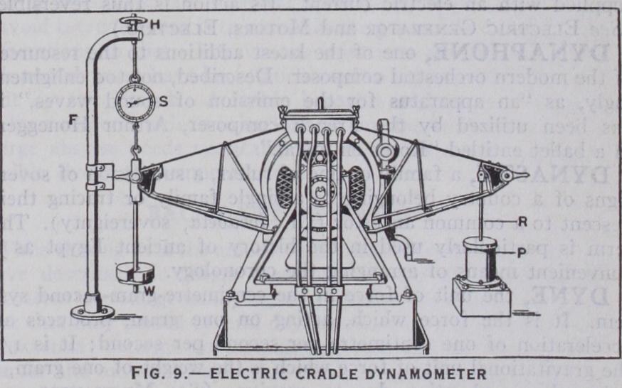
Electric dynamometers based on this principle are widely used to measure the power of high speed engines. Fig. 9 is an illustra tion of the electric dynamometer coupled to the Ricardo Ex perimental Petrol Engine. The engine shaft is coupled to the armature of the dynamo. The dynamo frame is held in ball bear ings only and is thus free to turn about the axis of the armature shaft. Attached to the dynamo frame are light arms. The arm to the left carries a scale pan W and is hooked to a spring balance suspended from a fixed support F and adjustable in position ver tically by the handwheel H. The arm to the left is connected to the piston of a dash pot P by the vertical rod R. Small oscilla tions are controlled by the dash pot. When the engine is running under load, weights are added to W and the hand wheel H is ad justed to keep the pointed end of the arm at the centre of the scale on the fixed support. The load, derived from W and the spring balance reading multiplied by the perpendicular distance of its line of action from the axis of revolution, measures the reaction T against which the armature is turned. A machine de signed by F. W. Lanchester to test the efficiency of worm gears may be classed as a dynamometer since frictional loss in a worm and wheel is measured directly by weighing the reaction the fric tion produces. A description of this interesting machine, set up in the National Physical Laboratory will be found in Appendix Q of a paper entitled "Worm Gear," read before the Institution of Automobile Engineers, Proceedings Session 1912-13.
W. W. Beaumont, "Dynamometers and Friction Brakes," Proc. Inst. C.E. vol. xcv. (London, 1889) ; E. Brauer, "Ober Brems dynamometer and verwandte Kraftmesser," Zeitschrift des Vereins deutscher Ingenieure (Berlin, 1888) ; J. J. Flather, Dynamometers and the Measurement of Power (New York, 1893) ; F. J. Jervis-Smith, F.R.S. "Dynamometers," edited by C. V. Boys, F.R.S. (Constable & Co., London ; J. S. Glen Primrose, "Dynamometer Car" (Engineering, June 25th, 192o) ; R. G. Batson and J. H. Hyde, "Mechanical Testing" (Chapman & Hall, London, 1922) ; G. W. Watson, "Recording Dynamometer for Tractors" (Engineering, June 3o, 1922) ; "A New Fan Brake Dynamometer" (Automobile Engineer, April 1923). (W. E. D.)