
ELECTRICAL EQUIPMENT Electric Motors.—The principal industrial motors are as fol lows: (a) Direct current—series, shunt, compound. (b) Alternat ing current—squirrel-cage induction, squirrel-cage induction "across-the-line" type, slip-ring induction, synchronous. For a description of the principles and capabilities of these, the reader is referred to the article on MOTOR, ELECTRIC.
The principal control operations required by an industrial motor are starting, stopping, speed adjustment; and protection of the machine under all circumstances. The control gear may be hand-operated or automatic, the degree of automatic operation varying according to the amount of responsibility that may still be reposed in the operator. For example, the apparatus may be controlled by automatic switches, or "contactors," every one of which may, however, act only at the will of an attendant, who is provided with small "pilot" switches or a "master controller" for governing the movements of the units that actually make and break the main circuit. Again, the rate of acceleration only may be decided automatically, in accordance with the loading condi tions; and thus the motor safeguarded while at the same time all unnecessary delay is avoided. Finally, the whole of an elaborate series of operations may be effected solely at the instance of a set of relays without any human guidance whatever.
The two principal control methods that combine to bring about the complete government of an electric motor are, first, the mak ing and breaking of circuits, and secondly the variation of the voltage applied to a winding, such as that of an armature, rotor or stator. The latter function may be achieved by varying the amount of resistance in series or parallel with the winding, and this again usually requires the making and breaking of auxiliary circuits by exactly the same means as were needed for the former function. Voltage variation may however be performed directly and with greater efficiency, for example by regulating the field of a generator, and thus the use of resistors may be largely avoided in heavy equipments. In the case of induction motors, a reduced voltage is frequently obtained by means of an auto-transformer.
The chief types of control apparatus may be tabulated as fol lows : (a) Manual apparatus—(I) switch type, (2) face-plate type, (3) drum type, (4) liquid type. (b) Automatic apparatus— (I) contactor type, (2) variable voltage type.
Manual Apparatus.—The simplest piece of manually oper ated control gear is of course the switch, in which one or more pairs of contacts can be brought together by hand. Of the various patterns, the knife switch is the most common, enabling an effi cient contact to be made by means of a simple and compact device. In its usual form, however, it does not lend itself to frequent use (such as once every i o sec.) , and it is generally employed as a main isolating device for putting the whole equip ment into commission at the beginning of the working period.
A single switch may be employed for starting any induction motor, or a D.C. shunt motor up to or t h.p., a compound motor up to about 2 h.p., and a series motor up to 8 horse-power. Above these sizes, the rush of current due to the low armature resistance and the absence of counter E.M.F. when at rest necessitates the use of a preliminary stage of resistance. "Push" switches are very useful for starting the smallest motors and for controlling small currents generally. Large oil-immersed switches may be used for making and breaking the stator circuits of high-voltage (e.g., 3,00o volt) induction motors or of lower voltage motors of large rating where the currents are of considerable magnitude.
The face-plate starter or controller is really a radial distribut ing switch for cutting out successive steps of resistance. It is a cheap and compact device, and enables a comparatively heavy contact pressure to be maintained without demanding a corre sponding force to move it. Nearly all manual starters for D.C. motors up to ioo h.p., and most A.C. resistance starters for small motors are of this type; but it is only adapted for making the simplest changes in the circuit, and hence starters for cage motors which reduce the voltage to the stator by other than resistance means almost invariably employ another pattern. It is also not adapted for robust service, i.e., for the frequent breaking of large currents, and it is usually designed to make the currents only, all breaking being done by a knife switch before the starter arm is automatically released by a "no-volt" or "under-voltage" retaining magnet.

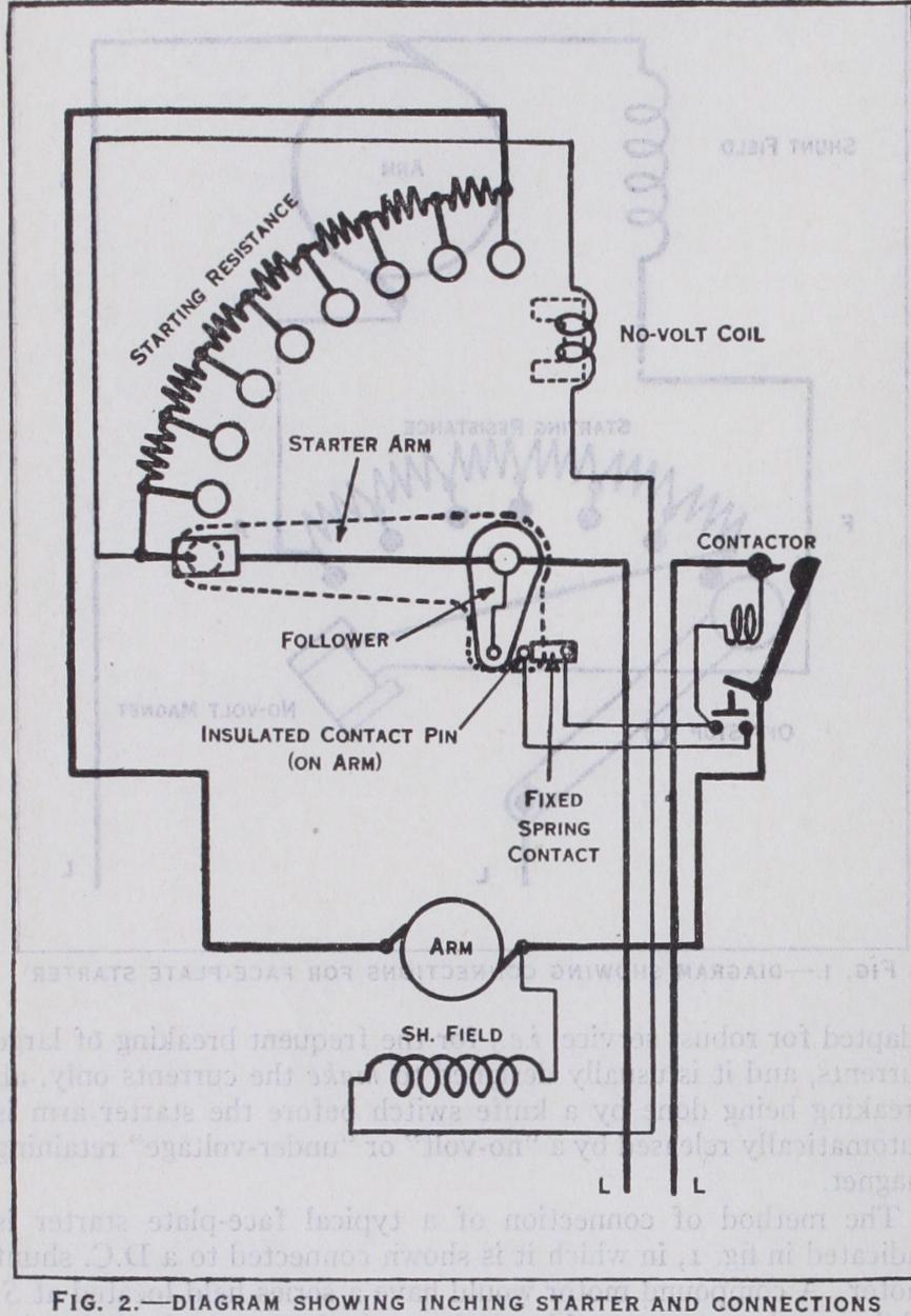
The method of connection of a typical face-plate starter is indicated in fig. I, in which it is shown connected to a D.C. shunt motor. A compound motor would have a series field located at S, while a series motor would only have the latter, the lead that in cludes the shunt winding in the figure being omitted and the no volt coil connected across the line in series with an appropriate resistance. A more elaborate face-plate starter arrangement is shown in fig. 2.
When used for almost any of the various industrial purposes, the face-plate should be protected by enclosing it with a metal cover.
For frequent service, heavier duty, and more elaborate changes of circuit, a drum starter or controller is used, in which the mov ing contacts are sector-shaped and are clamped on to a square spindle covered with insulation; and the fixed contacts are "fingers" with heavy copper renewable tips forced against the sec tors by spring pressure. A powerful magnetic blow-out is always fitted for all but the smallest sizes ; and a locating "star-wheel" device, which enables the operator to halt the contacts exactly in engagement.
Typical D.C. drum controller diagrams corresponding in many respects with the face-plate scheme in the last figure are shown in figs. 3 and 4 ; but the drum sectors are duplicated to give both for ward and reverse running from the same handle. As before the motor parts are shown in place on a reduced scale. The sectors are represented by horizontal strips and the fingers by large dots. Both these diagrams are for series motors, but the provision for the shunt winding can easily be made as for the face-plate type. It should be noted that with reversing installations, the shunt field must be itself shunted by a non-inductive "discharge resistance." Drum starters, either air-brake or oil-immersed, are also used for squirrel-cage motors when (as is usually the case for motors over 5 h.p.) local regulations require starting at reduced voltage, obtained by the use of a step-down transformer, or by connecting the stator windings first in star and then in mesh.
Liquid rheostats are suitable for use with any type of motor, but especially with those over about i 5o h.p. which start under load for which the previously described manual equipment is not well adapted. They are especially suitable for the absorption of large amounts of power.
In all but the largest, the "dippers," or moving contacts, are moved in and out of the liquid; but in the largest models (viz., up to and exceeding 2,000 h.p.), the plates are fixed and the liquid is caused to rise by means of an electrically driven pump. When the apparatus is used for controller duty, cooling pipes are im mersed in the liquid. The weir-type controller, in which the height of the liquid is regulated by the moving of a weir mechanically connected to the driver's lever, is a variant of the rising liquid starter. The principal advantages of the liquid type are the inde structibility of the resistor, smoothness of acceleration, cheapness and suitability for the largest sizes. Chemical action is absent with alternating currents.
Contactors may be normally-open or normally-closed, the con tacts in the latter case being pulled open by the energizing of the coil. D.C. models are sometimes designed to hold themselves open until the current in the main circuit falls to a given value, when they close : this characteristic being required for automatic acceleration by the cutting out of resistance. Series and shunt lock-out contactors belong to the latter category.
Fully automatic characteristics are given to contactor installa tions by means of relays, the chief varieties of which are included in the following list: Current-limit, time limit, float, pressure, overload, low-voltage, inching, torque, step-back, change-over, field-accelerating, field-braking and field-protection relays. Of these, the first two are the most important, since they provide for automatic acceleration without requiring lock-out contactors, the use of which has its limitations. Current-limit relays permit their contacts to close when the peak current, due to the switching in of the motor or the cutting out of a previous step of resistance, falls to a predetermined value, whereupon the next accelerating contactor is caused to close. Time-limit relays bring about closing of the accelerating units at definite time intervals. The former method is appropriate for heavy and fluctuating duty, such as rolling-mill auxiliaries and general industrial control; and the latter for such loads as air-compressors, pumping, ventilating, etc. Float and pressure relays are employed for starting and stopping the operations for the latter type of load.
Examples of the various types and arrangements of contactors and relays will be given in succeeding sections. It will be suffi cient here to indicate that most contactor diagrams consist of a line group and an accelerating group, which are connected in series in the case of D.C. motors, but form the stator and rotor circuits in the A.C. cases.
Auxiliary switches, such as push-switches, master-switches and master-controllers, are employed in the handling and general con trol of contactor installations ; and interlocks, both mechanical and electrical, are added to prevent the consequences of improper operation, e.g., two contactors of opposite polarity making contact with the one lead.

Variable voltage control is nearly always effected by the use of a motor-generator, set apart for the supply of the D.C. motor to be controlled, and caused to develop the voltage required at any stage by virtue of the field regulation of the generator. The ar rangement is exemplified in fig. 7 and is usually termed the "Ward-Leonard system." An A.C. supply is presupposed, driving the induction motor of the motor-generator, which also often includes an exciter for the two D.C. fields, though in large sets this may be a separate unit. The main driving motor is shown on the right, and this is started, stopped, reversed and regulated at any speed by the corresponding variation of the generator voltage by means of the reversing potentiometer-type field rheostat. The scheme will be seen to dis pense with resistors in the main circuit, all switching and adjust ment being carried out upon the exciting current. Since the field flux of even a moderate-sized dynamo changes gradually, the con trol is remarkably smooth and sensitive. Ward-Leonard control is especially appropriate for securing very wide speed regulation, and for use where preliminary creeping speeds are required.

If the induction motor is equipped with a fly-wheel and given a variable speed characteristic, by connecting a fixed resistance in its rotor circuit, or preferably by employing a variable slip regulator which introduces resistance in proportion to the over land peaks, the motor-generator is now able to store energy during light-load periods and to give it back during overloads. This is called the "Ilgner system," and possesses the great advantage of much reducing the maximum demand on the line. It also renders a much smaller induction motor suitable. Large rolling-mill drives are usually of this type.
Other methods of producing partial voltages without the use of resistance, which are suitable for small powers, are the series parallel system employing two motors, and the multi-wire sys tem, in which more than one voltage is given by the factory dis tribution. These methods however have only a limited application for industrial work.