
ELECTRICAL POWER GENERATION is accom plished almost entirely in two ways; utilization of power obtained from burning fuel, generally for steam generation, and the utiliza tion of natural and created sources of water-power for hydro electric generation.
The term electric power applies to a continuous supply of elec tric current through wires from central generating points in quantities sufficient for the operation of motors, heaters, lights and equipment for doing work electrically. This power may be in the 'form of direct current, i.e., that which flows always in the same direction around the circuit, or in the form of alternating current, which rapidly reverses in direction of flow. Each has its special uses in industry, in homes and on the farm. The generat ing points of electric power are termed power plants, generating stations or central stations, and are commonly located in large cities or at other points close to large centres of use. The power requirements which they satisfy are termed the "load." In the generation of electric power from fuel, the heat energy of the fuel is first converted into mechanical power by a prime mover, and then into electrical power or current by a generator. The principal prime movers in use in 1939 were the steam turbine and the hydraulic turbine (see TURBINE, WATER). In isolated plants of small capacity, and in marine plants, primary power is often derived from oil and gas engines, and it is possible to obtain it from various other prime movers such as windmills, tide ma chines, etc., although these latter are inefficient and cumbersome and therefore seldom used.
Development.—In the United States the steam turbine gen erates about 6o% of the total electric power, while most of the remainder is derived from water-power (see below under "Hydro electric Generation") . In other countries the ratio is differ ent, depending upon the available supply of commercially useful hydraulic energy and upon relative fuel costs. In the early steam station reciprocating engines were used exclusively, and the power was generated by direct-current dynamos. At about 10,0oo h.p. both the reciprocating steam engine and the direct-current ma chine reached their practical limit of size, and a serious question arose as to how the output could be increased at reasonable cost. Engineers then turned their attention to the steam turbine, which Parsons in England had used successfully in 1897 to drive a British naval destroyer. In 1903 a Curtis turbine was installed at the plant of the Chicago Edison Company and there success fully drove a generator of 5,000 kilowatts (6,70o h.p.) capacity. The problem of greatly increased power in less space was thus solved by the turbine, which was even then as efficient as the reciprocating engine. The use of alternating current, also, made possible the economical transmission of power over considerable distance, thus bringing electric service to communities far from the generating point. Since 1903 both turbines and generators have been greatly improved in design, until to-day single units of 280,000 horsepower are practicable and have been built. (See ELECTRIC GENERATOR.) In general no limit to capacity can be set. Economic considerations lead to generating units of very large capacity, few in number, rather than to many small ma chines, but in each case the local conditions determine just how large a single machine should be. Every central generating station is an individual case, and its design depends upon local conditions, such as amount and character of land available, kind of fuel. source of condenser cooling water, and the kind of electrical load served. In addition to steam generating equipment (see STEAM GENERATION, BOILERS), stations are structurally divided into (a) generating room, (b) bus structure, (c) switching and trans former equipment, and (d) control room. These elements will be discussed in the following paragraphs, after which a description of an actual modern central station will be given in order to illustrate the principles involved.
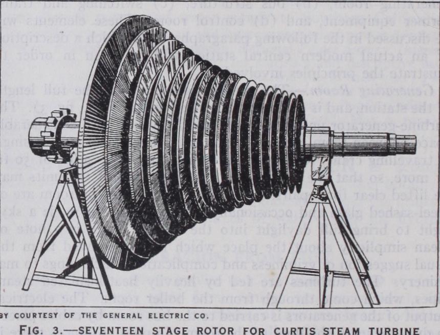
Generating Room.—The generating room runs the full length of the station, and is comparatively narrow (see P1. I., fig. 3) . The turbine-generator units are installed side by side with considerable space between them, and are completely enclosed in steel casings. A travelling crane, resting on heavy I-beams, gives a lift of 5o ft. or more, so that the casings and rotating parts of the units may be lifted clear for repairs. Often the end walls of the room are of steel-sashed glass and occasionally the entire roof is made a sky light to bring full daylight into the room. There is a note of clean simplicity about the place which is far removed from the usual suggestion of griminess and complication which clings to ma chinery. The turbines are fed by heavily heat-insulated steam pipes, which come through from the boiler room. The electrical output of the generators is carried to the bus room by cables placed in ducts beneath the floor of the room. In most instances there is little other equipment on the generating room floor besides the main units, although in some cases small separate turbine-generat ing sets are installed there to supply current for station auxiliaries and lighting circuits. Directly beneath the generating room the condenser well is located, the condensers themselves being bolted directly to the under sides of the turbines or connected to them by flexible joints, although in many stations this well is part of the main room, the turbine units being installed on platforms built above the condensers. The well usually contains the circulating pumps, air and hot-well pumps, and feed water heaters, together with the air-cooling system for the generators. Boiler feed pumps and evaporators are placed between the condenser well and the boiler room.
Bus Structure.—The bus structure is composed of heavy copper conductors supported on insulators and installed in concrete cells. It is the concentration point for all generated power, from which it is drawn by branch lines called feeders, going to the various points of use. Practice differs widely as to the number and ar rangement of the buses, but the principle is that of pooling the output of several machines so as to give the greatest flexibility. Each generator is provided with several oil switches, by which it may be connected to any bus desired. Instrument transformers, permanently connected to the generator circuits, furnish current and voltage to actuate the ammeters, voltmeters, wattmeters, and watthour meters placed on the panel boards of the control room. Many of these instruments are of the recording type.
Switching and Transformer Equi pment.—If the station is supplying nearby load, the feeders will pass directly from the bus structure to the pole lines or underground cable ducts, delivering electrical service at generated pressure. Groups of switches are used to connect the feeders to one bus or another for most eco nomical operation according to load. If the station output is to be transmitted to distant load centers, the electrical pressure must be raised in order that the reduced currents which result, may cause a smaller resistance loss. As the pressure is increased the cur rent is proportionally reduced for the same power. This permits the use of smaller conductors and at the same time causes lower losses, with consequent saving both in construction and operating costs. To effect this raise in pressure (voltage) large power trans formers are used, and these may be connected between generators and buses, or between buses and feeders. For this type of service, switching is usually done between transformers and transmission lines by high-voltage oil circuit breakers.
Switching and transforming equipment is often installed out doors and is designed to withstand any weather conditions. Stations in congested districts, such as New York City, usually have indoor switchhouses, feeding into underground cables.

Control Room.—This is the operating headquarters of the sta tion. Here the meters and instruments which indicate and record the electrical flow in all circuits are mounted on an easily accessible switchboard, and here are located the switches for controlling the circuit breakers, and the lamps which indicate to the oper ator the condition of every piece of apparatus. By means of signal buttons and telephones, orders are transmitted from the control room to the boiler and generating rooms, so that the attendants may be instructed to carry out the operations not included in switching. In some stations there is no control room as such, the meters and control switches being located on vertical boards placed in a gallery above the generating room.
The progress of power through the station, then, is briefly as follows (see Flow Diagram) : Steam flows to the turbines, gen erates rotating power, is exhausted into the condensers and is returned as water to the boilers. The generators change the me chanical power to electric power, which is measured, concentrated on buses, and switched to the proper circuits. These circuits either distribute directly to nearby loads, or carry the currents to trans formers which step up the voltage for transmission to distant points. Control and supervision of all station operations is centred in one room.

The Condenser.—The condenser carries out the reverse func tion of the boiler, reducing steam to water. It consists generally of a large number of parallel bronze tubes set in a vacuum-tight casing. Cold water is pumped through these tubes and the exhaust steam is condensed against their outside walls, falling to the bot tom of the casing into a chamber called the hot well, whence it is pumped back to the boiler.
Steam Auxiliaries.—In addition to the turbine and condenser there are various auxiliaries necessary for satisfactory turbine operation. They are, chiefly : (a) Steam strainers and valves, (b) turbine governor, (c) bearing oil system, (d) air pump, (e) cir culating pump, (f) hot-well pump, (g) feed-water pump, (h) drip pumps, (i) feed-water heaters, and (j) evaporators. The various elements will be taken up in the order of their use.
Strainers and Valves.—A metal screen is placed in the main steam supply pipe to catch foreign material which may be in the system. The steam then passes through a hand-operated throttle valve into the turbine. This valve is used for starting and stopping only.
Governor.—It is necessary to have a mechanism to provide the turbine with an amount of steam just sufficient to enable it to carry the desired amount of load. This is called the governor, and operates, through a hydraulic system, a series of valves ad mitting steam to the turbine nozzles. By adjusting the governor to admit more or less steam, the machine will attempt to run faster or slower than standard speed, but will be held to this speed by its generator which will automatically take a larger or smaller share of the electrical load of the system.

Bearing Oil System.—Turbine bearings are of the cylindrical type and are lubricated and cooled by oil which is forced through them by a pump geared to the turbine shaft. A separate steam driven pump is usually employed during the starting up period. To dispose of the heat in the oil, coolers are provided in which water is made to circulate, the heat sometimes being delivered later to the feed-water system. A large oil reservoir is usually built into the base of the turbine.
Condenser Pumps.—In the design of the modern power station the matter of a plentiful supply of cooling water for the con densers is of prime importance. It is necessary to locate the station close to a river, harbour or lake, because the quantity of water needed is very large. In the big stations, as the Rich mond station in Philadelphia or the Hell Gate station in New York city, a flow of condenser water of many thousands of gallons per min. is required. This water can be used only once since it becomes ineffectual as a cooling medium as soon as its tem perature has been raised by passing through the condenser. It is therefore pumped through the system and then discharged into the river. Centrifugal pumps are employed for circulating the cooling water, and these are driven by electric motors or small steam turbines. Each condenser has its own pumps, usually in duplicate, so that an accident to one pump will not rob the con denser of water and thus force the turbine to be shut down, be cause of lowered efficiency. Turbines are provided with atmos pheric exhaust valves, but these are used only to avoid blowing up the machine in cases of condenser failure. The cooling water circulates through the bronze tubes of the condenser where it re ceives the heat from the steam and leaves the condenser about 15° higher in temperature than on entering. In regions where there is wide variation between summer and winter temperatures and consequent warm cooling water supply in summer, the vacuum will be reduced and the turbine efficiency cut down. An ejector or vacuum pump is connected to the condenser to remove air and other gases which do not condense and which tend to destroy the vacuum. These gases have either leaked into the turbine through packing glands, or else have come through with the steam from the boiler. A hot well or sump is located at the bottom of the condenser to catch the water. A pump is placed here to start the water on its journey back to the boiler. There may also be other pumps in connection with certain steam auxiliaries, as for instance the drip pumps, which take the condensed steam from the feed-water heaters and evaporators and return it to the hot well or feed-water line.
Feed-water Heaters.—The simplest steam power cycle passes the steam through the turbine and exhausts it into the air, an inefficient method which uses less than 1 o% of the heat energy in the steam. By adding a condenser and returning the water to the boiler the efficiency of the cycle can be doubled. But there is still a large quantity of heat lost in the condenser to the cool ing water. It is possible to capture some of this heat before it reaches the condenser by extracting a certain quantity of steam from the turbine at various stages of its expansion and while it yet contains considerable heat energy. This extracted steam is used to heat the boiler feed-water. The principle of interstage feed-water heating is that of using the heat energy of the steam at high temperatures rather than of allowing it to escape into the condenser where the temperature is so low that feed-water heat ing cannot be accomplished. The boiling point of water rises with a rise in pressure and for this reason the temperature of the boiler feed-water can be very much higher than the atmospheric boiling point (212°). The water coming from the hot well of the con denser is usually between 70° and loo° F and may be heated to 300° or 400° before entering the boiler. The process is carried out in heaters consisting of casings containing nests of pipes sur rounded by steam extracted from the turbine. It is common prac tice to have several heaters in series, each one contributing per haps 50° to 10o° to the temperature of the feed water. The steam used in these heaters must be hotter than the water heated, and the feed-water progresses from heaters of lower temperature to those of higher. The supply for each heater is therefore taken from the turbine at a point where the necessary steam tempera ture exists. By careful calculation it is possible to determine an arrangement of heaters which will give the maximum use of the heat sent into the turbine in the steam. The number of heaters ranges from one to five, and the steam they use may be as much as 25% of the total supplied to the turbine. The heating steam condenses in each heater and goes to the heater unit of the next lower temperature, and finally to the drip pump and into the feed-water line.
Feed Pumps. The water is forced into the boilers by feed pumps located somewhere along the line between the hot well and the boiler. These pumps are usually of the centrifugal type, driven by electric motors or by steam turbines.
Evaporators and De-aerators.—There is, inevitably, a slight loss of feed water from the system. This loss may be made up by pure water supplied by evaporators. These are stills heated by steam drawn from the turbine. Raw water is evaporated in them and passed to a small condenser whence it is discharged into the feed water line. A small amount of dissolved air is also car ried out of the condenser by the water, and may be removed by a de-aerator before it reaches the boiler. (For a fuller description of these boiler auxiliaries, see STEAM GENERATION.) The steam apparatus commonly used in the modern generating plant is subject to many variations. In very large turbines the volume of the steam may be so great that it is sent into them at the middle, passing out at both ends. This is called the double flow turbine. Mechanical limitations may make it impossible to build a single turbine which can handle the volume of flow re quired for very large powers. In this case two separate turbine cylinders are used, each with its own rotor. One unit operates on high pressure and exhausts into the other. Both are on the same shaft, and drive a single generator. This is called a tandem compound machine. The giant turbine in the State Line station in Chicago, rated at 280,000 h.p., is of the cross-compound type. It is virtually three separate turbines ; a high-pressure unit receiving steam from the boiler, and sharing its exhaust between two low-pressure units. All three have separate shafts and sepa rate generators. It is becoming the practice with compound tur bines to pass the steam exhausted from the high-pressure unit, through a resuperheater in the boiler, to regain the initial tem perature without raising the pressure. This gives the important advantage of dry steam throughout all the turbine stages.
Development.—The fundamental factor in modern electric power generation and transmission is the use of alternating cur rent. In the early days it was thought necessary to produce and sell direct current, and for this purpose direct-current machines were built exclusively. They were large and costly because of the provision which had to be made to change the alternating current generated within the machine to uni-directional current for outside use.
During the later '8os alternating current was strongly cham pioned by George Westinghouse who, with the aid of William Stanley, produced in 1886 a commercially practical transformer and thus opened the way to alternating-current electrical distri bution. Since 189o, central station development has been along alternating-current lines, with the exception of a few installations in Europe where direct-current generation and transmission is used. For certain purposes, such as for trolley or tram cars, direct current is universally employed, as also in many railroad electrifications. This current, however, is obtained by feeding alternating-current power from the central station to outlying substations, where either synchronous converters or mercury arc rectifiers convert it to direct current. In some districts the original Edison three-wire direct-current distribution system is still used, the supply being derived from substations which have large installations of storage batteries for use during severe peak loads or when emergencies interrupt the normal supply. The Generator.—The alternating-current generator (see ELEC TRIC GENERATOR) operates on principles discovered about ioo years ago (see ELECTRICITY). A hollow cylindrical steel element, the armature or stator, contains groups of insulated copper conductors. Within this armature a cylindrical rotor is placed, called the field. The field contains a series of coils so arranged that the passage of a direct current through them produces on the sur face of the rotor or field a series of magnetic north and south poles. Thus a two-pole generator has one north and one south pole, a four-pole machine, two of each kind, and so on. As the rotor re volves the magnetic flux at the poles sweeps around the cylindrical inner surface of the armature, cutting the armature conductors with magnetic lines of force. Currents are generated in the con ductors of the armature, depending for their magnitude, voltage and rate of change (or frequency) upon the speed of the rotor and the number of its poles. A complete alternation of current in the armature conductors is called a cycle and is obviously the result of one whole revolution of a two-pole rotor, or of one-half revolution of a four-pole rotor, etc. In order to give satisfactory service the rate of alternation or frequency of the generated cur rent must remain essentially constant, and this is done by regu lating the rotating speed by the turbine governor. Twenty-five, fifty and sixty cycles per second are the frequencies to-day.
Modern central station generators are designed to give current at the highest voltage or pressure consistent with safety of in sulation. Ten to 14 thousand volts is common practice. Early generators delivered current from a single set of conductors into a single external circuit, requiring two wires. It is the modern practice to put three windings on generator armatures, so con nected that there are three external wires, of which any one pair is carrying current independently. In other words, each wire be longs to two different circuits and is carrying two different cur rents at the same time. It is thus possible to generate and transmit about twice as much power with three wires as with two. This is called the three-phase system. Certain classes of machinery, such as converters, may employ as many as twelve phases, though the economic advantage for transmission is practically exhausted with three.
House Service Generators.—The present tendency in central station design is to drive the auxiliaries such as pumps, etc., by electric motors. Current for this purpose is provided by service generators, which are small low-voltage machines built on the main generator shafts. Thus each main unit has its service generator, so that when the turbine is running it supplies its own auxiliaries and is independent of outside sources of supply. For starting up, the auxiliary motors are connected to a current supply generated by other turbines already running, or provided from sources outside the station.
Exciters.—The direct current for the rotating field is supplied by a small generator called the exciter, which is usually built integrally with the main generator on the end of the latter's shaft. By manipulating this "exciting" current (which is relatively small and of low potential) very close control of the main generator voltage is obtained with simple equipment which is usually lo cated in the control room.
Cooling.—The conductors in the generator are made as large in cross-section as is possible in the space available, so that they are of very low resistance. However, the flow of current through any conductor whatever causes some resistance loss, which ap pears as heat in the conductor. Furthermore, some heat is gen erated in the iron of the core by the rapid changing of the mag netic flux (see ELECTRICITY). This heat amounts to only about one per cent of the generator output, but is numerically large in large machines. In a 6o,000 kilowatt generator, for instance, the loss might amount to 600 kilowatts—enough to run a small fac tory or light a whole street of private homes. The heat losses may be dissipated by placing a fan on the end of the shaft to circulate air through the spaces between armature and rotor. With large machines it is now general practice to enclose the machine entirely and to force air through it with external cen trifugal blowers. A recent design returns the warmed air to a cooler known as a surface air cooler, in which water circulates in a nest of pipes similarly to the steam condenser. This permits the same air to be used over and over again, thus avoiding the large quantities of dirt likely to be brought in by new air. Still higher cooling efficiency is obtained from a scheme now coming into use, using a single gas such as hydrogen instead of air. This is based on the fact that more heat can be absorbed by hydrogen than by an equal volume of air. Less gas therefore can be used, thus cutting down the size of blowers, coolers, etc., and reducing the friction loss occasioned as the gas passes over the surfaces to be cooled. Blowers are usually driven by electric motors, and installed in duplicate to assure dependability.
Lubrication.—The bearings of the generator are of the same self-aligning type as those of the turbine. They are lubricated and cooled by the same oil as for the turbine and are included in the same piping system.
Fire Protection.—The compounds with which the generator insulation is impregnated are somewhat inflammable, and if elec tric arcs are accidentally started within the machine a destructive fire may develop. There are various automatic schemes for warn ing the station attendant of a generator fire and for spraying water on the windings, or for replacing the circulating air by CO2 or some other inert gas which will smother the fire. The tempera ture of the windings is also carefully watched upon an indicating meter on the switchboard. This meter is connected to small coils within the machine, which are carrying a steady current. A rise in temperature of the main windings changes the resistance of these coils and causes the meter to indicate it. (See THER MOMETRY, Electrical resistance type.) Temperature indicators are sometimes arranged to give audible warning of excessive heat ing or even to shut down the generator by automatic means when the danger point is reached.
Handling the Current.—The current from the various gen erators is pooled upon a conducting structure known as the bus system. There are usually several buses, so connected as to pro vide a star, or ring-shaped, path for the current. The generators are attached to the bus system by individual lines so arranged that in case any section of the bus becomes inoperative the generators feeding that section can be reconnected through alternative paths to the portion of the bus still in service. In the larger stations the buses are elaborately sectionalized, the sections being installed in separate fire-proof vaults. Trouble on any section is met by disconnecting that section completely, and shifting the load upon it to some other section. The buses and bus sections are con nected together through oil circuit breakers, and the generators are connected to them in the same way. These circuit breakers are operated by small electric motors or solenoids, which are set in motion by switches in the control room. They are usually equipped with tripping relays which cause the breakers to open their circuits when dangerously heavy currents flow in times of accident. In many stations the feeder circuits are provided with current-limiting reactors which prevent the flow of de structive short-circuit currents and the consequent lowering of the voltage over the whole system. They have no appreciable effect upon normal power currents. Reactors are also frequently used between bus sections. A bus is composed of a group of heavy copper bars or cables rigidly supported on insulators, one conductor for each of the three phases. Modern practice is tend ing toward the isolated phase arrangement, in which each con ductor is installed in a separate concrete room or gallery, often on a separate floor of the building from the other phases. Isola tion is also sometimes effected by enclosing each bus in a grounded metal shield. These elaborate precautions are taken to avoid the spread of electrical fires starting from burnouts or short circuits, and thus to increase the reliability of the station. Metering Transformers.—The load currents are too large and of too high a potential to allow of their being sent directly through meters. To get around this difficulty, small transform ers are connected into each generator circuit and each feeder circuit, the secondary windings of which supply to the meters small low-voltage currents, which are proportional to the load current and voltages. (See TRANSFORMERS.) These transformers are designed to operate without consuming an appreciable amount of power. The current transformer consists of an iron core and secondary winding associated with a straight heavy conductor which is part of the main circuit. The potential transformer is a miniature power transformer with a primary winding placed across a phase of the main circuit and the secondary winding feeding the meter. Both types operate on the principle of a cur rent induced in a winding by the action of a fluctuating magnetic field.
Control Room.—The switching of the generators and feeders and the apportioning of the load among them, is managed from a central switchboard. This consists of a number of vertical panels upon which there are mounted the meters and the recording in struments for reading the current, voltage and power. A desk or horizontal portion in front of the board is provided with rows of pull-button switches, which are connected through low-voltage circuits to relays on the various circuit breakers. When energized by pulling out the buttons, these relays connect the electric operating mechanisms of the breakers to a power supply circuit and open or close them as the case may be. Red and green lamps on the board are associated with each relay so that an indication is given of the condition of the breaker.
A signalling system, somewhat similar to that employed on shipboard between bridge and engine room, is installed between the control room, boiler room and generating room. If the operator wishes a generator started up he presses the proper button, which actuates a signal beside that generator. The at tendant starts the machine and, when it is up to speed, the operator synchronizes it with the system with the aid of a syn chronizer. When the incoming generator is "in phase" it is switched onto the desired bus. The turbine governor is then ad justed by means of remote control so that the generator will take whatever amount of load the operator wishes it to carry.
The operation of all station equipment is correlated in the con trol room, so that the station as a whole produces and sends out power when and where it is needed. By means of a totalizing instrument the sum of all the outgoing feeder currents is indi cated on the switchboard, so that the operator can start up ma chines or stop them as the load-demand requires. An indication of the totalized demand is also given in the boiler room, to assist the fire-room attendants in supplying enough steam, and in an ticipating changes in station output.
With the enormous quantity of energy required in the present day metropolitan area, it is usually necessary to join a number of central stations together on a single network, often backing them up by hydro-electric power sent in from a distance over transmission lines (see ELECTRICAL POWER TRANSMISSION). In such a system, the control room of any one station is but a sub ordinate point, the real control resting with the "chief load dis patcher," whose office may be at any convenient location in the district.
Like the railway train dispatcher, the power dispatcher has executive charge of the movements of great quantities of power. He has before him a board on which are plotted the various sta tions, trunk feeders and interconnections with other power sys tems. With the aid of telephones and signals he commands the units of power generation and coordinates his own system through interconnection points with other systems, constituting a great network which may distribute power over a radius of hundreds of miles.
The Arrangement of a Large Generating Plant.—In or der to unify the discussion of the various details in the foregoing paragraphs, a description of the 380,00o h.p. Richmond station of the Philadelphia Electric Company is given below. This station is an excellent example of standard practice, embodying no ex tremes, and yet combining simplicity of arrangement with high efficiency.
Richmond Station is located in Philadelphia on the Delaware River where an adequate supply of cooling water for condensing purposes is always available. The boiler house, generating room and switch house are located in adjacent buildings, the boiler house being next to the river. Next is the generating room and beyond that, the switch house. Cables carrying the electrical energy away from the station run from the switch house to large industrial customers and to the company's distribution sub stations, also to an outdoor transformer and switchyard located at some distance from the main building.
Boiler House.—The boilers are arranged in 2 rows on opposite sides, with a firing aisle between. Coal is received at the plant in river barges, from which it is hoisted by grab buckets. It is passed through crushers to belt conveyors on which it is weighed and then distributed to overhead bunkers located between the two rows of boilers. It is then fed by gravity through pipes to the stokers which are driven by variable-speed electric motors. These stokers force the coal into the furnace underneath the fire in the required quantities. The ash, on leaving the furnace, is broken up into small particles by grinders driven by the stoker motor, and then drops into hoppers which are emptied into ash cars running on a narrow gauge railway on the basement floor (for description of other methods of handling ashes, see ASH HANDLING, MECHANICAL HANDLING). The cars in turn are emptied into an outdoor pit, from which the ashes are removed by a grab bucket and loaded on freight cars, trucks or river barges for final disposal.
Air for combustion is provided by a forced draft fan located on the top of the boiler. This fan forces the air through preheaters, where it is heated to a high temperature by hot flue gases, and then into the furnace. Two induced draft fans draw the gases from the furnace and direct them up the stacks.
An instrument board is provided adjacent to each boiler, on which are mounted instruments which indicate to the operator the amount of water being fed to the boiler ; the pressure of steam; pressure of the air being supplied to the furnace for combustion; the pressure of gases in the boiler; the stoker speed (which indi cates the amount of coal delivered to the boiler) ; and the amount of air being supplied for combustion.
Generating Room.—This is a large, well-lighted vaulted room next to the boiler house. The two original units are 6o,000-kilo watt, 13,800-volt, three-phase generators driven by 20-stage tur bines installed on platforms or "islands" about twenty-seven feet above the ground floor. In the space provided for a third 6o,000 kilowatt unit, a 165,00o-kilowatt unit was installed and placed in operation in 1935. This gives some idea of the progress in tur bine-generator design during the preceding period of ten years. The governor mechanism is located at the boiler room end of the turbines, and the controlling inlet valves are located beneath the floor.
The condenser for each of the generator units is placed directly beneath the turbine, and is supported on concrete foundations through counterweighted levers which compensate for expansion. On one side of the condenser, on the basement floor, are located the motor-driven circulating pumps, each of which takes water at the rate of 78,000 gal. per min. from concrete intake tunnels extended under the boiler house to the Delaware river, and forces it through the condensers and back to the river. The older and newer pumps are of the centrifugal and propeller types respec tively.
Duplicate motor-driven fans, located adjacent to the generator foundation, provide cooling air for the generator. This air circu lates through the generator over and over again, being cooled each time before entering the machine by a surface air cooler supplied with water by the condenser circulating pump.
The steam which has passed through the turbine is exhausted into the condenser, from which it is drawn in the form of water by means of condensate pumps. This water is then delivered through a series of heaters back to the boilers where it is again transformed into steam. On a platform beneath the turbine floor the first feed-water heater is located, taking steam from the 18th stage of the turbine. Just beneath this is a Radojet air ejector which assists in maintaining a high vacuum in the condenser. The steam used in the jet is later made to heat the feed-water. The water is then piped to a gallery between the generating room and the boiler room, where it passes through two more feed-water heaters supplied with steam from the 12th and 15th stages of the turbine, and finally through the boiler feed pump. This pump is of the centrifugal type, operating at about 500 lb. pressure, and driven by an electric motor. In this gallery also, the evaporators are located, arranged to be cut in aad out of service as additional water is required for the system. Above the heaters on a high platform there is a surge tank for each unit—a device to equalize the variations in supply to the feed-water system.
Generators.—Each generator is installed on a common base with its turbine and is totally inclosed. Each machine has its own exciter carried on the end of the shaft. Instead of the small service generator attached to the turbine shaft, as mentioned previously in this article, the source of power for auxiliaries essential to the continuous operation of the station, is provided by a transformer bank connected to the main generator terminals in such a way that the generator may be disconnected from the buses without interrupting the supply to the auxiliaries. These transformers, together with other transformers which supply the less essential auxiliaries from the main station buses, are situated outdoors in an areaway between the generating room and the switch house. An emergency service set consisting of a small turbine-generator is provided, being installed in one corner of the generating room.
Switch House.—Beyond the generating room is the switch house which is housed in a four-story structure and is an example of the isolated phase system. The three phases are placed each on a separate floor, phase "A" being at the top. Generator and feeder oil circuit breakers are grouped in concrete cells with asbestos doors which are kept locked. The circuit breakers and their dis connecting switches are operated by vertical rods coming up through the floors. The operating mechanism for each breaker and the handle controlling the disconnecting switches are in stalled on the ground floor below phase "C." There are two buses separated from each other by a longitudinal wall, and each bus is divided into two sections. Each generator and feeder circuit is provided with a main oil circuit breaker, and through another oil circuit breaker, known as the "selector" breaker, may be connected to whichever main bus is selected for operation. The feeder circuits are carried through current-limiting reactors and thence by cables in concrete ducts to the underground distribution system and to the transformer yard.
Transformer Yard.—This is a fenced enclosure situated at some distance from the station proper. The feeders from the switch house connect to two transformer banks which change the voltage from 13,80o to approximately 66,000 volts. From the transformer banks, the energy is supplied to the Philadelphia Electric Com pany's 66,000-volt system and to neighbouring utility companies.
Control Room.—The control room is located on the fourth floor of the power house over the transformer areaway between the generating room and the switch house. It has a wide bay window which affords the station operators a clear view of the generating room. The operator sits at a desk, in telephonic com munication with the system load dispatcher in the city, and with the generating room and the boiler room. The system load dis patcher determines the amount of load which the station is to carry, and issues directions for any major switching operations. In addition to telephonic communication between the control room and the generating room, a hand-operated indicating tele graph is provided for each generating unit for signalling between these points when placing a unit on the line or taking it off.
Before the operator are three switchboards, arranged in a semi-circle, one behind the other. The first is a bench-board or desk-like structure, divided into panels, each panel controlling a generator or several feeders. On this board are groups of small switches by which the operator opens and closes oil circuit breakers, adjusts the load and excitation of the generators, etc. The second board is a series of vertical panels, on which are mounted all meters and instruments for the generators and feeders. The third is the relay board and on it are mounted protective relays which automatically disconnect from the buses any circuit in which trouble may have developed. On this board are also located small switches and fuses for the low-voltage circuits from which the oil circuit breakers are controlled.
On each side of these three main boards there are 2,400-volt panels with control switches, meters and relays for controlling and metering the house-service circuits. One of these panels controls the steam-driven service generator.
Below the control room is a conduit or "pipe" room, in which all conduits carrying control and metering wires converge from all parts of the station. On the floor below the pipe room are the direct-current power rooms, in which are located motor-generator sets and storage batteries which supply power for energy excitation of the generators, emergency lighting, and for the operation of stoker motors and oil circuit breakers.
These are the main features of the Richmond station. In this building is space for a fourth turbine generator, originally in tended to be of 6o,000-kilowatt capacity. The next addition to this station will be a "superposed" unit using steam at 1,200 to 1,40o pounds pressure and then passing it on to be used in the present units at the lower pressure of 375 pounds per square inch.
G. Tarboux, Electric Power Equipment (1932) ; F. T. Morse, Power Plant Engineering and Design (1932) ; A. H. Lovell, Generating Stations ; G. H. Gaffert, Steam Power Stations (1937) ; F. W. Gardner, "British Practice in Steam Turbine Design" Transactions A.S.M.E. (1933) ; G. H. Gaffert, "Extraction Heaters in the Power Plant," Power Plant Engineering (Aug., ) J. N. Landis and S. A. Tucker, "Performance of Two ioi,000-Square Foot Surface Condensers" Transactions A.S.M.E. (1934) ; W. A. Carter and F. O. Ellenwood, "Thermal Performance of the Detroit Edison Turbine Using i000° F. Steam" Trans. A.S.M.E. (1935) ; A. H. Lovell, T. C. White, R. Bailey, F. R. Ford, A. P. Fugill, C. M. Gilt, "Switch ing at State Line, Richmond, Connors Creek, and Hudson Avenue Stations," Trans. A.I.E.E. ; A. M. Cushing, "Design and Opera tion of Huntley Station No. 2," Trans. A.I.E.E. (1935) ; "The Rich mond Station of the Philadelphia Electric Co." Electric Journal (Jan. 1936). (D.O.W.; X.)