
ELECTRICITY SUPPLY: TECHNICAL ASPECTS.
The supply of electricity may be either (1) a private supply on a small scale foi electric lighting in an isolated country house, hotel, institution or ship, or else on a large scale by a railway company or local authority for purposes of lighting, traction, or power for their own use; or it may be (2) a public supply by a limited company, corporation, local authority or government for general supply of electric current to the public for light, heat, power or other purposes. In the latter case the commodity sold is energy in the form of electric current supplied for a certain time at a specified voltage or pressure and reckoned and charged for at a certain price per kilowatt-hour or Board of Trade unit. (B.T.U.).
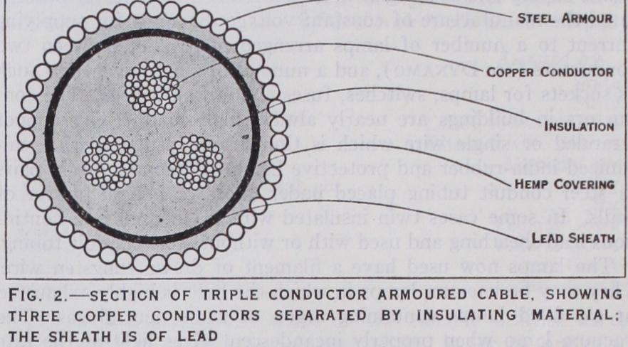
The invention of the carbon filament, electric incandescent lamp in 188o and 1881 by T. A. Edison, J. W. Swan and C. H. Stearn made possible domestic electric lighting by private and public supply and this began to be undertaken in 1882. It necessi tated the manufacture of constant voltage dynamos for supplying current to a number of lamps arranged in parallel between two conductors (see DYNAMO), and a number of small inventions such as sockets for lamps, switches, fuses and switch-boards. The con ductors in buildings are nearly always high conductivity copper stranded or single wire which is tinned and insulated with vul canized india-rubber and protective hemp. These are run in pairs in steel conduit tubing placed under floors or behind plaster of walls. In some cases twin insulated wire is enclosed in a contin uous lead sheathing and used with or without steel conduit tubing.
The lamps now used have a filament of drawn tungsten wire. They may be vacuum lamps in which the bulb is highly exhausted or gas-filled lamps containing argon or some neutral gas. The vacuum lamp when properly incandescent gives light at the rate of 1 watts per candle power and the gas-filled lamps about watt per candle power (c.p.) . Hence a 16 c.p. vacuum lamp takes about 20 watts.
If perfect security from interruption of supply is required then the engine and dynamo plant must be duplicated, each part being equal to maintaining the full supply. The engine-room must be equipped with current and volt-measuring instruments and cut outs and switches so that the engineer in charge can know at all times the state of the plant and have control over it. In the building itself the main supply cable from the storage cells termi nates at a main switch-board of slate or marble fitted with double pole switches and fuses for each branch circuit. These branch circuits run without break or joint to distributing boxes on the various floors from which again sub-circuits are run to each room. These sub-circuits terminate in double-pole fuses on the distribut ing boards. No such circuit should carry more than 1 to 3 amp. of current. The whole wiring installation should be put in in accordance with the wiring regulations of the Institution of Elec trical Engineers or of the principal fire insurance offices to secure safety from fire. The insulation of the whole installation should be tested on completion of the wiring contract.
The Institution of Electrical Engineers' (I.E.E.) rule for direct current installations is as follows. The insulation resistance with all lamps and fuses in place and switches on shall be measured by applying between earth and the whole system of conductors, or any section thereof, a direct current pressure of not less than twice the working pressure and the insulation shall not be less than a number of megohms equal to 25 divided by the number of lighting points on the system. Thus for a 'co-lamp installation it must not be less than megohm.
For private country-house installations there is a very extensive use of small direct current dynamos coupled direct to an internal combustion engine worked with petrol or paraffin, and these are so arranged that they may be operated without skilled labour. This generator is commonly associated with a suitable storage battery so that the plant can be run during the day and stopped at night. With care a good battery should last 15 years but the life of the positive plates can easily be very much abbreviated by careless use, overcharging or allowing to stand unused and partly discharged.
In this system (see fig. 1) as used also for public supply, there are three bars on the main switch-board called positive, middle and negative, 02, 03. From these proceed sets of three under ground or overhead conductors called feeders, F1, F2, which run to the area of consumption. They connect into three other sets of conductors called distributing mains, D1, D2, D3. The consuming devices H1, H2, either lamps or small motors, are con nected in about equal number in parallel between the positive (+) and middle main (M) and the negative (—) and middle wire (M). Between the positive and negative bus bars are con nected the direct-current generating dynamos giving a voltage equal to double that required for the lamps or consuming devices placed on the two sides of the middle wire. If the number of such lamps or total current taken by them all is equal on the two sides of the middle wire then this last will serve merely to distribute the current differently to lamps on the two sides of the middle wire. If, however, the current demand on the two sides is unequal, their two shunt-wound direct current generators B1, B2 with very low resistance armatures have to be joined across the outer mains in series and their junction point connected to the middle wire. These machines are called balancers. If then the outgoing current in the positive main is greater than the return current I2 in the negative main, the difference called the out-of-balance current, returns along the middle wire. Half of it passes each way into the balancer armatures. The machine on the negative side becomes a motor and drives the other machine as a generator and the latter supplies the out-of-balance current.

The equality of voltage on the two sides is improved by con necting the fields of the balancers in series across the outer mains but so that the current enters the field of the negative side bal ancer first at that end nearest the negative main. If it is desirable to employ storage batteries to assist supply at heavy loads or for supply during the night then each battery on the two sides must have in series with it a direct current dynamo called a booster to add to the main generator voltage the extra volts of o.6 volt per cell required to charge the batteries. These boosters have their shafts directly coupled to the balancers and are driven by them. The booster voltage is regulated by resistance inserted in their shunt-field circuits. The ideal condition desired is that the main generators should work under constant load so that when the external load of lamps or other devices is light, the battery would be charged, and at times of heavy external load the battery would discharge and supply the excess current required, the terminal voltage remaining all the time constant. This condition, however, is difficult to fulfil, but many connections of boosters, such as the Highfield, approximate to it. If a booster is used simply to supply the extra charging volts of a storage battery it is called an "irre versible" battery booster. In this case it is a shunt-wound gen erator and is driven by a motor fed from the main circuit. If the booster is a series-wound machine it can be made to add or subtract voltage so as to keep the circuit volts constant. In this latter case it must have its field magnets of well-laminated iron so that the voltage generated shall follow quickly the variations of current. Such a booster is called a reversible battery booster. There is an extensive use of boosters, called negative boosters, in traction supply systems to prevent the potential of the return rail from becoming too high relative to the earth and to prevent the flow of current through the earth which does damage to water and gas pipes. The advantage of the three-conductor system is that it effects a saving in copper in the mains for the same supply voltage at the lamp terminals and the same percentage energy loss in the mains. This saving may amount to as much as 62.5%.
Three-conductor direct current supply systems are in common use in which the generators supply current at 44o volts and the lamps and consuming devices on the two sides are worked at 220 volts. This is about the safe limit for domestic supply for lighting.
At this point some information may be given about supply conductors. These are either aerial (or overhead) or underground. The aerial lines are constructed with well-seasoned fir poles im pregnated with creosote in the below-ground portion. They may be single poles or multiple poles of A or H shape. For heavy currents high voltage lines they are steel lattice towers 5o to 15o ft. in height tapering upwards and of square or triangular section. These poles or towers carry cross arms to which are attached single or else chains of porcelain insulators according to voltage. The conductors themselves are of hard drawn copper wire and sometimes aluminium or steel-cored aluminium wire. These lines are spaced apart from 2 to 12 ft. according to the voltage used. Single-phase alternating requires a pair of lines and three-phase f our lines. At intervals disconnecting switches are placed and essential adjuncts of an aerial line especially in mountainous countries are lightning protectors which consist in some arrange ment, generally two horn-shaped iron rods, by which, if lightning strikes the line, the discharge can get to earth over a small gap or through an electrolytic cell, but the line current cannot follow to maintain an electric arc discharge and so short circuit the line or put it to earth. On aerial lines voltages as high as 150,000 or even 250,000 volts are used. The transmission of power by small electric currents and very high voltages raises many practical problems of great difficulty. The high voltage on the line ionizes the air molecules near it and produces on the line a glow discharge called a corona. This involves a dissipation of energy which may be at the rate of several kilowatts per mile of overhead line. (For details see The Electrician, Oct. so, 1913, p. 13.).
The "capacity effects," as they are termed, associated with long underground cables, call for special means of connecting or disconnecting them in order to avoid the production of electric surges. Electricity flowing in conductors behaves like a very heavy incompressible fluid. It cannot be started into motion instantly and when flowing cannot be arrested suddenly without means for nullifying its inertia. Long concentric cables must not be switched suddenly on or off the bus bars or switch-boards of alternating current supply stations but the current must be fed into the cables slowly through a variable resistance to avoid sudden pres sure rises due to combined capacity and inductance which might break down the cable insulation.
Two other similar large hydro-electric stations exist in the Rhone valley near and above Martigny to supply the Simplon railway running from Lausanne through the Simplon tunnel to Baveno and Stressa. One station, called the Barbarine station is high up on the Salvan pass and the other is at Vernayaz in the Rhone valley. There is another station at Thusis, near the entrance to the Via Mala, which supplies similarly current to operate the Rhaetic railway which runs from Coire to St. Moritz in the Engadine and to Davos. The electric locomotives on these electric lines are of 1,200 to 2,100 h.p. the latter being able to draw a train of 500 tons up an incline of 1 in zoo at a speed of 40 m. an hour. This electrification of the main lines has greatly increased the average train speed and especially the comfort of working on lines with many long tunnels such as these main Al pine lines. The electric supply lines are duplicated to secure safety and generally follow different routes. The transformers are in iron cases filled with insulating oil and these are placed in the so-called outdoor stations in which transformers and switches are arranged in the open air under a steel lattice framework which supports the insulators and these the connecting bars.
There are in France three-phase alternating current stations in which the alternating current is rectified or converted to a di rect current for railway working. The direct current motor has many advantages over the single-phase or three-phase alternating current motor in that the weight per horse power is much less and the arrangements for controlling the speed much more simple. There are practical limits to the voltage which can be used for direct current motors. It is, however, quite a simple matter to build such motors for 1,200 to 2,000 volts. On the other hand the alternating current can be raised in voltage easily by static transformers for transmission and lowered again for use. The practical problem, therefore, which electric traction supply systems involve is that of converting alternating current into direct cur rent. This can be done in one of two ways (i.) by rotary con verters and (ii.) by mercury arc rectifiers. The first method uses an alternating current induction motor supplied with three-phase alternating current which is coupled direct to a direct current generator which gives current at 500 volts or 1,200 as required. The direct current is supplied to the motors of the locomotive or of the car by an overhead trolley line or by special side rails, and returned by the main rails. This arrangement is widely used on the urban electric railways in London and other large cities. It involves, however, moving machinery and therefore manual attendance.
In one form used for railway working the tube consists of a large steel box in which a high vacuum is created by a pump. In the bottom is a pool of mercury which acts as the cathode. In the lid of the box there are six glands through which iron rods pass air-tight and insulated electrically. These rods are con nected to the two outer ends of the terminals of the three circuits on a three-phase transformer and the central junction to the mercury cathode. The mercury vapour then acts as a rectifier and converts the three-phase alternating current into a direct current. For further details special treatises must be consulted. (See J. A. Fleming, Mercury Arc Rectifiers and Mercury Vapour Lamps.) Public Electric Supply.—The idea of supplying electric cur rent for lighting purposes to a large number of users from a common supply station seems to have occurred about 1878 to St. G. Lane Fox in England and T. A. Edison in the United States (see British Patent specifications Nos. 3988 and 5306 of 1878) and was put in practice in New York in 1881, in London in 1882, and by Col. R. E. Crompton in Vienna in 1883-84. The early attempts met with many difficulties and had only a limited range of operation due to the use of a two-wire direct current system with 1 oo–I I o volts pressure between the mains. Crompton em ployed in Vienna a five-wire 44o volt direct current system. J. Hopkinson and T. A. Edison had devised the three-wire system, already explained, in 1883 as a means of extending the range of the direct current system. In 1884-85 S. Z. de Ferranti, who had already invented an alternating current dynamo, patented an im proved form of transformer (British Patent No. 15141 of 1885 ) and soon after developed a system of alternating current supply in which electricity was generated at a high voltage, even 1 o,00a volts, and transmitted by underground mains to certain trans former stations where it was converted to low pressure and dis tributed to users at a convenient voltage. Similar systems were devised by Ganz, Westinghouse, Elihu Thomson, Parker and Mordey. S. Z. de Ferranti was unquestionably the pioneer of alternating current high voltage supply. His financial supporters erected a large station at Deptford in 189o-91 for supplying a part of London, and this London Electric Supply Corporation overcame in time many of the early difficulties of such supply due to capacity effects in the mains and insulation. The alternating current system had great advantages in dealing with an area of scattered users in that the high voltage permitted a small current to convey a considerable amount of power and this demanded only transmission lines of small section. In the early days with the exception of the Ferranti system a very usual voltage of supply on the alternating current system was 2,000 volts on the high tension side for generation and transmission reduced to roo volts by transformers for use in houses.
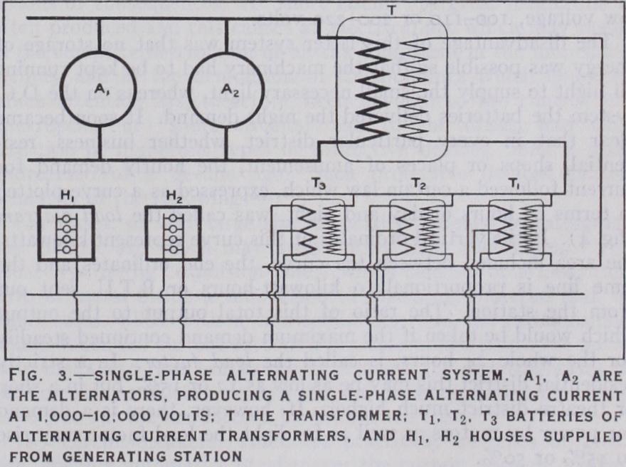
The three-wire system can also be applied to alternating cur rent supply as well as direct current (fig. 3). Two systems of public electric supply were therefore developed and much put in practice between the years 1882 and 1892 in all parts of the world for public electric supply. One of these was the three-wire direct current system, using dynamos generating at 220 or 44o volts connected across the outer mains, with balancers, boosters and batteries across the two side circuits. This was called the D.C. system, and was found very suitable for the central parts of large towns and thickly populated districts. The other, called the A.C. system, employed alternators and transformers and in country districts overhead high tension mains and distributed to houses at low voltage, r oo–r r o or 200-2 20 volts.
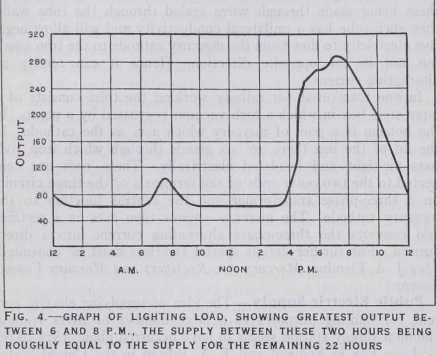
The disadvantage of this latter system was that no storage of energy was possible so that the machinery had to be kept running all night to supply the small necessary light, whereas on the D.C. system the batteries delivered the night demand. It soon became clear that in every particular district, whether business, resi dential, shops or places of amusement, the hourly demand for current followed a certain law which, expressed as a curve plotted in terms of hours of day and night, was called the load diagram (fig. 4). If the vertical ordinates of this curve represent kilowatts, the area included between the curve, the end ordinates and the time line is proportional to kilowatt-hours or B.T.U. sent out from the station. The ratio of this total output to the output which would be taken if the maximum demand continued steadily for the whole 24 hours, is called the load factor. In a strictly residential district this may be as low as r 2 or r 5 %, but in a shop or theatre district much higher. If, however, there is a demand for power by motors as well as for light the load factor may rise to 45% or 50%.
The earliest type of ampere-hour meter was the Edison zinc sulphate electrolytic meter, but the trouble in reading it caused it to be soon replaced by mechanical meters. These are in effect small electric motors which the current drives round against a cer tain retarding force which is proportional to the speed. The number of revolutions made by the meter in a given time is recorded on dials like those of a gas meter. If the driving force is proportional to current passing then the dials record quantity of electricity or electric energy on the supposition that the supply voltage is constant. If the driving force is proportional to the electric power passing then the dials record true electric energy in kilowatt-hours. A large number of such motor meters have been invented, such as those by Ferranti, Elihu Thomson, S. Evershed, Chamberlain and Hookham, the Sangamo meter (Edison, Swan Electric company) and others. Some of these, such as the Elihu Thomson motor meter, are suitable both for direct and for alter nating current. Others, such as the Schallenberger meter, depend on electro-magnetic repulsion and are only applicable on alternat ing current circuits. The most usual form of tariff is the flat rate in which the consumer is charged by meter for the units of electric energy actually taken, but owing to the fact that the chief demand for electric supply is for electric lighting and this is determined by the daylight hours and by the customary times for meals and rising and retiring to rest, the lighting supply demand runs up into a sharp peak at certain hours. The object of the various tariffs which have been introduced is therefore to encourage a demand for electric power taken either uniformly, or else at hours when the lighting demand is small for electric cooking, heating, and driving small domestic motors, etc., by giving such supply more cheaply than at the flat lighting rate.
The most common variation on the flat rate is some form of fixed charge depending on the total number of lamps installed and then a charge for electric energy supplied at a much lower than flat rate. (For the various types of tariff in use see J. W. Meares, Electrical Engineering Practice, ch. xv.) Extra High Tension National Electric Supply.—The in creasing demands for electric energy for power purposes and the numerous and very different supply pressures, voltages and systems have caused great attention to be directed to the problem of national electric supply in Great Britain. Briefly, it is proposed to construct over Great Britain a large system of overhead or aerial conductors consisting probably of steel-cored aluminium cables supported by appropriate insulators on steel lattice towers. The system of supply is to be three-phase alternating current at a frequency of 5o cycles and at a pressure of r 3 2,000 on the main conductors. This system of mains is called the "gridiron" and will have put into it current from selected or constructed stations. From these mains electric current can be tapped off and reduced in pressure by transformers for any required purposes at any place on the route. The "gridiron" will consist of three conductors, one for each phase and doubtless a fourth conductor connecting the neutral points of the three-phase star connected circuits. Special precautions will be taken against the production of steep-fronted electric surges travelling along these lines due to lightning. The gradient of atmospheric electric potential is gen erally at the rate of r oo or r 5o volts per metre, the earth in fine weather being negatively charged. Under thunderclouds, however, the gradient may be many hundred times as great. This means that induced electric static charges are created on an aerial line, and this is, in the old-fashioned language, a "bound" charge. When, however, the thundercloud is discharged by a lightning flash this bound charge becomes free and its potential may be added at some instant to that of the line. The result may be a flash over at an insulator which for a moment puts the line or one phase of it "to earth," at a certain place. The result is to produce an electric wave of potential which travels away along the line. If the difference of potential between two near points on the line is very large this is called a steep fronted surge. If such a surge passes back along the supply line into a transformer or alternator it may cause a great difference of potential between adjacent turns of wire and so cause a breakdown of insulation and do damage expensive to repair. Accordingly, many devices have been invented called surge protectors for stopping these steep-fronted surges from travelling along electric supply lines. One of these consists of a peculiar form of electrostatic condenser which is joined across the lines. When a surge comes along it darts into the condenser and expends its energy harmlessly. Another con sists of a form of low resistance choking coil with a secondary circuit of non-magnetic iron in which the surge dissipates its energy as heat. (For further details see J. A. Fleming, The Inter action of Scientific Research and Electrical Engineering, ch. vi., 1927.) Electric feeders or supply lines conveying large currents are always laid in duplicate generally along different routes so that in the event of a breakdown on one line the supply is continued by the other.
Also automatic cut-outs or switches are placed at the ends, operated by relays or electromagnets, so that in the event of a "dead earth" occurring on one section that faulty section of the line is at once removed from the live circuit. These arrangements generally operate in virtue of the fact that in a line without fault or earth or short circuit the current leaving at the far end is the same as the current entering. If, however, a fault occurs then these currents are unequal and this may be made to actuate sensi tive devices called relays which in turn operate the terminal switches and cut out the faulty section of the line.
The technical aspects of public electricity supply have, in the main, been especially concerned with the production and distri bution of electric energy upon a very large scale. The extra ordinary growth of the use of electricity, which has resulted, in part, from the steadily declining costs of service and, in part, from the increase in the size and scope of general industrial ac tivity during the past decade, has been reflected in the advance of technical practice. Conversely, the increased efficiency in the use of fuel and the development of high-voltage power trans mission over comparatively wide areas have been, to a large ex tent, the principal factors in lowering the cost of electric service to the public and thus, in turn, in stimulating a demand which has made possible still greater efficiencies of production and distribu tion. Until a few years ago, the attention of the technicians of the electricity supply enterprises was primarily concerned with the perfection of power-production equipment and with the reduction of the cost of generating energy. The advances in transmission line practice and the wide-spread adoption of the concept of "interconnection" have, however, produced a tendency to build large power-plants at some distances from the centres of con sumption and have thus necessitated not only much specialized apparatus for successful delivery of this energy, but also of specialized operating practices.
The insulation of electric-carrying devices is, in fact, the foun dation of the electric power system. While it has been successfully accomplished in the lower range of voltages, very little is still known of its true character or the phenomena involved in its breakdown. The failure of insulation results in the escape of some of the electricity from its intended path and its travel either to ground or to another portion of the energy-carrying circuit. Where the amount of energy involved is large (as is usually the case where many power-plants are tied together in interconnected regional schemes) such a breakdown usually results in the most serious of consequences. A "short circuit" of great magnitude is often produced and this causes an electrical arc which may result in the complete destruction of all the equipment in the immediate vicinity and in the demolition of the buildings which house it. Much attention has, therefore, been devoted to the control and interruption of "short circuits" and to the design and con struction of numerous types of protective devices, upon a scale undreamed of a decade ago. Such protective devices consist primarily of the following (a) Fuses, of very large size, especially designed to extinguish any electric arc which may arise during their functioning. The usual type is the "expulsion fuse," which consists of a long, thin strip of metal inside a tube made of insulating material and, in some cases, filled with a non-conducting and fire-extinguishing liquid. When the current exceeds a pre-determined point, the metal strip melts and thus breaks the circuit and the resulting gases in the container suddenly expand and are discharged in such a way as to put out the arc formed by the melted fuse.
(b) Circuit-breakers, which are practically switches of great size, opening automatically whenever the current exceeds a given amount. They consist, in essence, of contacts between fixed and movable current-carrying parts, which contacts are broken when the mechanism is actuated. The contacts are submerged in oil, which smothers the arc formed when the circuit-breaker is opened. The apparatus is controlled and released by a very delicate device known as a "relay" which trips the opening mechanism as soon as the current through the line exceeds what is considered a safe value. Modern circuit-breakers to interrupt the current of large systems are enormous affairs and their functioning is usually of the order of an explosion. In such cases, their interrupting capac ity falls off rapidly with each successive operation unless they are overhauled and put in proper shape after each one. Because of the intensive carbonization of the oil when a heavy arc is formed in it, good practice usually dictates a complete change of oil after each functioning of a circuit breaker on high-voltage systems.
Several special devices have been employed with success in the control of smaller hydro-electric plants and substations located in regions which are remote and sometimes difficult of access. One such development is the automatic station, which is supervised by mechanism actuated from the central point of authority. Water power plants, up to a capacity of io,000 h.p., are operated in this manner in numerous sections of the country and eliminate, to a large extent, a personnel of considerable size.
(b) The "medium loading" district, comprising the North Pa cific coast, the Rocky mountains and a belt approximating the Piedmont region of the Southern States. Provision is made for 4 in. of ice and the same wind pressures.
(c) The "light loading" district, being the balance of the coun try and embracing the California coast, and the territory along the Mexican border and the Gulf and South Atlantic coasts. Here no sleet may be expected, but provision for lb. wind pressure (an indicated velocity of 92 m. per hour) is made.
Actual conditions throughout the country, together with proper design to withstand weights of ice even greater than the above, are still the subjects of much study and experimentation. An interesting method for the prevention of sleet has been success fully adopted by several Eastern regional schemes. This consists of the discontinuance of the transmission line as a carrier of the usual high-voltage energy and the transfer, through it, of con siderable current at very low voltages at recurring periods ranging from 3o min. to an hour. This heats the wires to an extent which inhibits the formation of ice upon them. This scheme is, however, practicable only where a large number of circuits are available, so that the several wires may be kept hot, in rotation, without making it necessary to discontinue service on the entire system.