
FOUNDING. In a broad sense, the art of founding may be described as making a hole in sand and filling it with fluid metal. In the cold state the metal retains the shape and contour of the hole and is to that extent a metal casting. The art of founding is practised in foundries for the production of castings in all the commercial metals and alloys, and the two main stages are (1) the melting to fluidity of the metal or alloy and (2) the making of a container or mould of the form required in the final casting.
Apart from range of temperature the general principles involved in the production of castings are common to all types of alloys and metals. A mould may be regarded as a receptacle to be filled with a hot fluid. Of necessity, the material of the mould must re tain its form and remain unaffected by the heat and washing ac tion of the fluid and, while retaining it, must be sufficiently porous to allow the air displaced and also any gases evolved to escape freely. A trapped air or gas bubble would result in a cavity and, according to the extent of such trapping, would militate against the soundness or solidity of the cold casting. Any disturbance of the surface of the mould by the washing action of the stream will result in the disturbed material being trapped within the casting and in the cold state will show as dirt and disfigurement.
In common with all hot liquids, molten metals used in founding lessen in volume during cooling; this liquid shrinkage is naturally more pronounced in the heavier castings, and it is met by keeping, at the highest parts of the casting, channels open for the supply of extra fluid to replace the shrinkage below. These open channels or feeding heads are continually fed with fluid metal until the casting has solidified. After solidification the law common to all hot bodies comes into play and the cooling casting contracts with the falling temperature. The various metals and alloys have differing contraction coefficients, but these are known and are therefore allowed for by making the mould larger in volume to that extent.
The features thus outlined represent the metallurgical side of founding and must be fully met in the production of sound and true castings.
This division of patterns simplifies the moulding operation. In the present instance, one half-ball is laid on a flat board and the bottom moulding box placed in position; facing sand is sieved over the pattern, the box filled with riddled floor sand evenly rammed, and the whole turned over on to a level sand bed. In this position the mould joint is ready made and the top-half pattern is placed in position by means of the guide pins (fig. 2) . The sand joint is dusted over with a parting medium of burnt sand in order to ensure a clean separation at the joint and the stage shown in fig. I is reached. The top-half box is fitted with snugs drilled with holes corresponding to the upright pins of the lower box, these forming a guide for the later return of the top-half box. Facing sand is sieved over the pattern ; a round feeding-peg is placed on the top of the pattern and a round runner-peg about 2" away from the pattern, and the top-half is then rammed with sand as is already the bottom. The sand is levelled off, the two pegs withdrawn and the top-half box lifted off bringing with it the top half pattern. This half is turned over in order to draw the pat tern. A small channel is cut in the bottom-half to form a gate from the bottom of the hole left by the runner-peg and to con nect it to the pattern. The bottom-half pattern is drawn, any loose sand removed, and both half moulds dusted over with a carbonaceous facing. Fig. 3 shows a section through the closed mould when the top-half box has been replaced and the runner and feeding cups are in position. Before casting the top-half box is weighted down to prevent its being lifted by the pressure of the liquid metal.
This outline covers the making of a simple mould and it is now advisable to examine some of the features introduced.
The sand in contact with the pattern is termed "facing sand," that not in contact but used only as a backing and for filling up the moulding-box, "black" or "floor" sand. The former gives the desired appearance ; the latter supplies the necessary rigidity and gives the mould a porous backing for the escape of gases. Black sands are simply the accumulation of used facing sands. All sands are worked in a moistened condition, but if too wet molten metal will not lie quietly on them. A ready test is that a ball of sand when squeezed should part cleanly from the hand ; adhering sand indicates excess water. The term "green sand" indicates a mould cast in the condition as moulded, that is undried. The term "dry sand" is applied to moulds made precisely as green sand moulds but dried in a stove before casting.
The reason for the condition of air porosity in a moulding sand will be appreciated by one who tries to fill a gas-tight vessel with a stream of water the full size of a small aperture into it. Unless the displaced air can escape through the aperture a moment arises when a certain amount of water is ejected. In a sand mould filling with fluid metal the air within the mould, or any gases generated, must similarly find an egress; hence the necessity for porousness, which is artificially increased by venting or pricking the sand with a wire to within a short distance of the pattern after ramming the mould.
The sphere of fig. 2, jointed in the centre, represents a clear draw; but there are cases where simple division is insufficient to ensure the clean withdrawal of each half pattern, and subdivision then becomes essential. Fig. 6 shows a type of recess met with in many castings. Owing to the taper a clean parting of solid pattern from sand would be impossible, so the pattern is made in three parts, the two loose pieces forming the inside taper being temporarily held in position by pegs as shown. The mould is made by placing the pattern flat side down on a turning-over board and laying the bottom half of the moulding box in position. The recess is rammed with sand ; the pegs are withdrawn from the outer edge of the pattern, and the ramming completed; the bottom-half box is turned over on to a sand bed and the joint made; the top part with runner-pegs is rammed up and lifted off ; runners are cut, and the main part of the pattern withdrawn, leaving the two loose strips remaining in the sand. The space provided by the removal of the pattern is sufficient to allow the strips to be drawn away horizontally until they clear the over hanging sand and can be removed vertically. Any projecting piece can be treated as a "loose piece," provided the space left after drawing the pattern is sufficient to admit of a side draw and then a straight lift for the removal of the loose piece.
The splitting of a cylinder into two halves would result in the same process of moulding as sketched in figs. 1 and 3. If the plain cylinder is replaced by a fluted column then a division of the pattern along its length would not give two halves admitting of clear drawing from the top and bottom boxes respectively. In such a case each half pattern would be split into three sections as shown in fig. 7. Moulding is carried to the stage of both half patterns being ready for drawing. On drawing the central part of each half pattern two side pieces remain in each half mould. These are removed in a direction suitable to the contour of the fluting so as not to break the sand forming the flutes. This method of pattern division is largely applied to ornamental and engineering castings.
Up to this point only the production of the external form of a casting has been considered ; but in practice very few are solids, the majority having an internal form. This may be simply for lessening weight or, as is more usual, for some utilitarian purpose. The household kettle is a ready example of a casting in which the interior is required for service, and utility of the interior of a casting is well shown in the cylinders of a steam engine or motor-car.
Core boxes are built in sections in order to allow the removal of the core when made. The division of a round or square straight-length core box is shown in fig. 8. The two half boxes are fastened together, a strengthening piece of wire or iron rod placed in the centre, and core sand evenly rammed to the top. A hole is pierced through the length by means of a vent wire, the box unfastened, one half lifted off, and the core is ready for removal. As the core is "green" it will not admit of free handling, therefore on removal of the half box a layer of floor sand is spread evenly over the exposed half core and a level surface formed on which an iron plate is laid. The whole is turned over plate downwards and the remaining half box lifted away, leaving the core sitting in a sand bed. The plate is lifted into a drying stove, and the core when dry may be freely handled. The purpose of the strengthening wire or rod is evident, and the vent hole pierced through serves as a channel for the escape of gases when the core placed in the mould is surrounded by molten metal except at its two ends.
The principle of loose pieces applied to core boxes is shown in fig. 9. The core box is so built that on removing one half box the loose strips remain in the core and may be withdrawn laterally.
Cores may take a more or less curved form. A half core box for an elbow pipe is shown in fig. 1o, and in this instance the method, though not the principle, of making the core will vary. Each half box is packed with sand and a strengthening iron bent to the required curve is bedded in one half. Both half boxes are strickled level and a coat of clay water pasted over the sand in each half to ensure sticking. Two strings are laid on one half so that their ends slightly overlap at the bent portion, the two half boxes brought together and tapped. The removal of the strings from each end of the box will leave a clear passage through the core. Instead of string flexible wax vents may be bent to the required contour and left in the core ; on drying the wax is absorbed by the sand and a clear passage remains. With large cores the most effective channels are formed by "ash vents," which are made by ramming and strengthening as usual and then cutting central channels in the sand. The cut portions are filled with small coke and the core finished off as usual. With large cores this type of vent offers the most effective route for the escape of gases.
Patterns are provided with core prints and when the cores are placed in the resulting imprints alignment is assured. Taking a flanged pipe as an example the core prints remaining in the half mould are shown in fig. 11, and the core when laid in these prints will leave a space in the mould as shown by the dotted lines. If the top half of the mould be fitted on with the core in position then the closed mould will offer the requisite space for filling with fluid metal to give a replica of the pattern plus the desired central hole.
The principles underlying the art of founding have been indi cated in their technical significance. As with all technical sub jects, extension of principle is possible. While a complete pattern and core boxes are essential to economical production of standard castings elasticity is possible in the production of odd castings. Skeleton or outline patterns are used and the extra time taken in making a mould from a guide pattern is, in the case of a few castings only, balanced by the time saved in making a complete pattern.

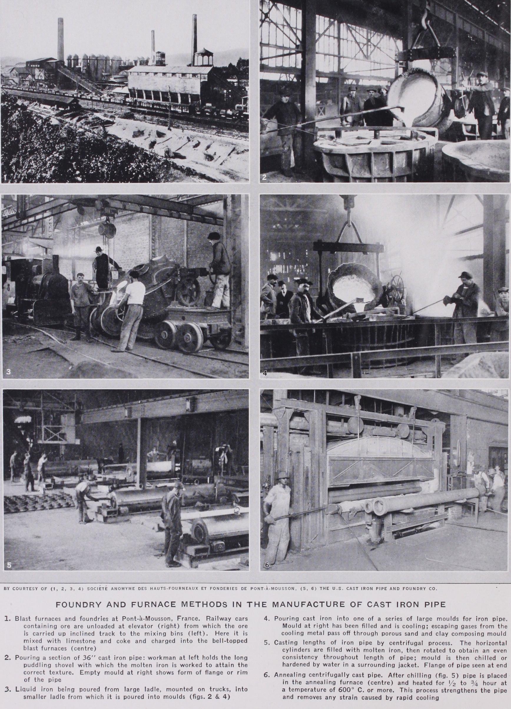
Nonferrous alloy castings may be made in permanent metal moulds ; research in this branch of die casting is proceeding and promising results have already been obtained. In other directions, notably with cast-iron water pipes, centrifugal casting in rotating metallic moulds is proving successful.
BIBLIOGRAPHY. Journal of the Iron and Steel Institute (half-yearly, Bibliography. Journal of the Iron and Steel Institute (half-yearly, 1871 etc.) ; Proceedings of the Institute of British Foundrymen's Assoc. and of the American Foundrymen's Assoc. (both. ann., 1892 etc.) ; T. Turner, Lectures on Iron Founding, 2nd ed., 1911, A. McWilliam, P. Lorgmuir, General Foundry Practice, 3rd ed. rev. 1920.