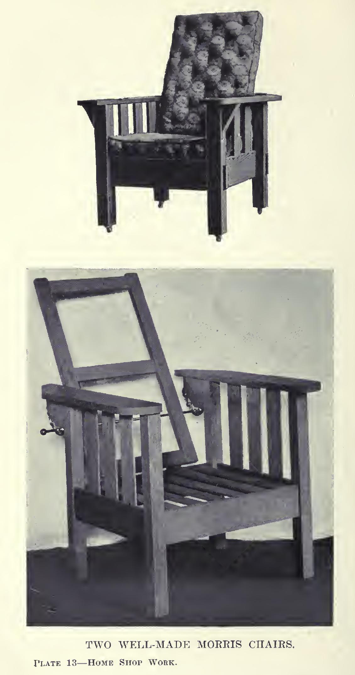
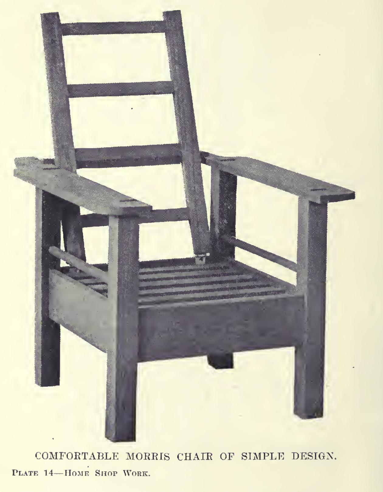
A Large Mission Rocker
inches, edge, inch, fig, mortises, slats, cut and rails
The mortises which are to be put on the sides of the back posts must be laid out at an angle with reference to the edge. The one at the top is to be % of an inch by 3 inches, placed so that its top shall be inches below the top of the post. The lower mortise is to be placed on a level with the one previously laid out on the for ward surface. It should be by inches. The proper angle at which to lay out these mor tises can be got by laying a straight-edge along the leg from the middle of one mortise to the middle of the other, the sides of the mortises being laid off parallel to this line and at the proper distance from it. They are to be cut to a depth of inches.

The rails for the back may be tenoned and mortised, the slats cut, and the back glued up next. The top rail is to be laid out to nineteen inches between the shoulders, leaving 1 inch at each end for tenons. Fig. 67 shows the settings of the gauge.
The lower rail is to be of the same length. Fig. 68 shows the settings of the gauge.
Before cutting the mortises for the slats in the rails, cut the five slats to length, inches. This allows for a tenon on each end. These tenons may be shouldered, as shown in Fig. 64, or the ends of the slats may simply be "housed" by making mortises just the size of the cross-section of the slats. The latter is easier, and will look and be just as well, pro vided the mortising is accurately done.
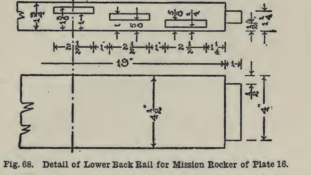
To lay out these mortises, place the two rails in the vise; even the shoulders and the edges. The under edge of the top rail and the top edge of the lower rail—the face edges—are to placed up. Begin midway between the shoulders, and lay off cross-lines for the five mortises so that there are five cross-lines inches apart—or whatever the slats measure in width—with 1 inch between, and inches between the last mortise and the shoulder of the end tenon. On the top rail, the gauge should be set first to then to % of an inch, in locating the sides of the mortise (Fig. 68). Cut these mortises 7/16 of an inch deep.
Clean up the parts thoroughly, and put the back in the clamps. Glue the ends of the slats but slightly. Make sure that the rails are square to the posts from face as well as edge.
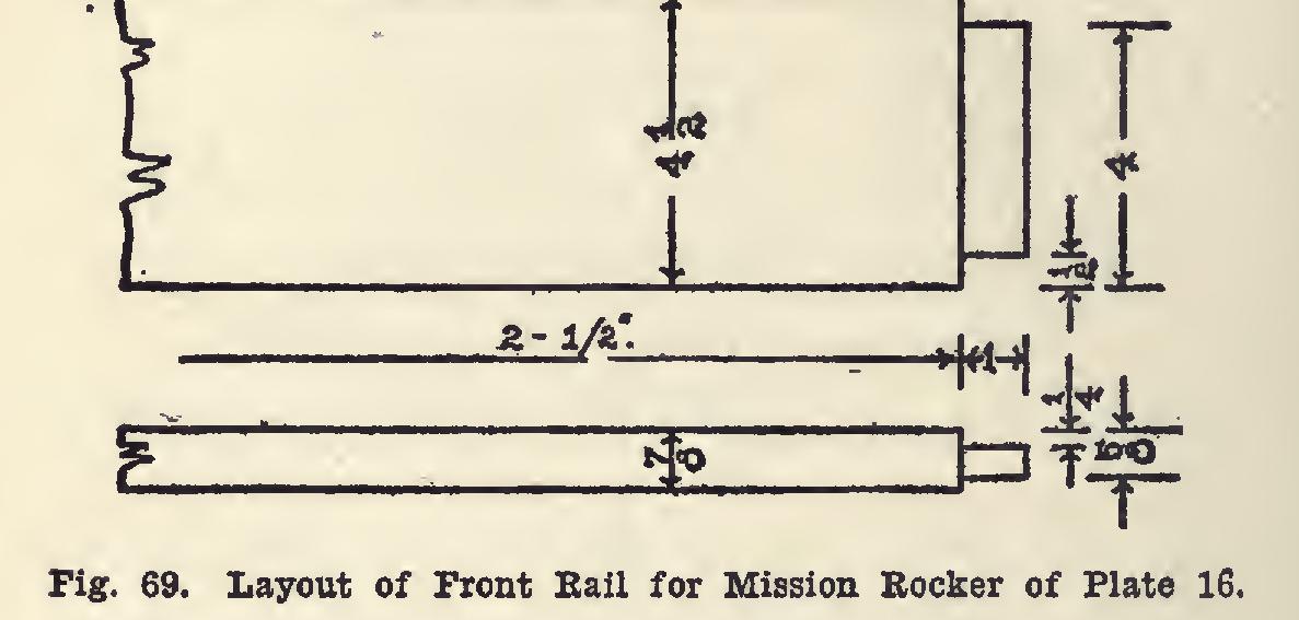
Fig. 69 gives the layout of the front rail. The distance between shoulders is 2 feet an inch. Cut the tenons, clean the pieces, and glue up the two front posts to them, squaring care fully from face and edge before leaving.
The tenons and shoulders of the side rails must be cut on an angle, the sides of the mor tises having been cut square to the surfaces. The T-bevel should be used to mark off this slope. Fig. 70 gives the layout. Lay the side rail on the bench, or place it in the vise, with the joint-edge up; lay on the steel square so that the outer edge of the blade will take the direc tion of the line A (Fig. 70), crossing the edge at the inch mark, while the tongue will take the direction of the line B, crossing the edge at the mark. Mark along the tongue, and also mark the edge at the mark, to indicate the length.
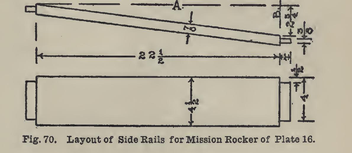
The T-bevel may be set from these marks, and the other edge marks put on with it. Lo cate the middle of these sloping lines, and meas ure each way of an inch, to get the position of the sides of the tenon. Place the steel square in a position similar to that just used, but with the blade on one of the tenon marks and the inch mark of the tongue on the corresponding tenon mark at the other end. iliark along the blade. Similarly, all of the tenon sides may be laid out on the edges. The gauge may be used to lay out the rest, setting it to inch and gaug ing from the joint-edge, then setting it to 4 inches (Fig. 70). Rip first, then crosscut to the shoulder lines.
The arms are to be 2 feet inches long. They taper from 5 inches at the front to 4 inches near the back, on a straight line, then by an easy curve to 2 inches. An offset of one inch is made, and the arm fitted to the back leg, after which the ends and corners are curved, as shown in Fig. 64.
The side rails should be cleaned, glued, and clamped to the legs so that they may dry while the arms are being made.
The mortises on the under side of the arms are to be just the size of the tops of the front posts, and should be laid off from the inner edge of the arm with try-square and gauge.
After the tenons have been cut, the rockers may again be placed, and the location of the mortises marked by superposition. Fig. 66 gives the gauge settings for the tenons.
If slats are used for the seat, as shown in Fig. 64, cleats must be screwed upon front and back rails, to which they may be fastened. They should be set low enough to allow the slats to rest about of an inch below the top edge of the rails.