A Morris Chair
inches, inch, legs, fig, edge, three-quarters, lines, inside and gauge
The vertical side bars are six in number, to be squared up to three-quarters, by three, by ten and one-half inches.
The two pieces for the arms (Fig. 54) are seven-eighths, by six, by forty inches. The fore part has the outer corner cut off, a three-inch radius being used. The back part is ripped to a gauge-line three inches from the inside edge, to a distance of seven and one-half inches from the end. The three corners are cut, an inch and a-half radius being used.

The gains into which the stick which sup ports the back enters are laid off by measuring from the end one and three-quarter inches; from this, mark three-quarters of an inch, then one and one-quarter, three-quarters, one and one quarter, and finally three-quarters of an inch. Set the gauge to five-eighths of an inch, and gauge, from the inside edge, the spaces between the lines three-quarters of an inch apart. Saw and chisel, keeping the saw kerf on the wood which is to be removed.
The mortises in the arms are to receive the tenons cut on the tops of the legs. Square lines across from the inside edge at points measured from the fore part three and one-half inches, from this point two inches, then twenty-two, and, finally, two inches. The gauging is done from the inside edge, the gauge being set to five eighths of an inch, then to two and five-eighths inches. Lay off both upper and under sides of the arm.
These mortises can best be cut by boring a series of holes pretty close to the lines, then chiseling from each side half-way through.
For the back, square two pieces to one and three-eighths, by three, by thirty inches. Bevel the top ends one-quarter of an inch. Place the two pieces on edge, and even the ends. Very carefully mark off, with knife point and try square, lines at the following points, beginning at the lower ends: Four inches, three inches, four inches, three inches, four inches, three inches, four inches, three inches. There should remain two inches. Carry these lines across the face and onto the other edge. Set the gauge to five-eighths of an inch, and, gauging from the face, mark between the lines which are three inches apart. Gauge both edges of each piece. These gains are to be sawed and chiseled so as to receive the cross-bars, of which there are four.
The cross-bars are three-quarters, by three, by nineteen and one-half inches, beveled on the ends one-quarter of an inch.
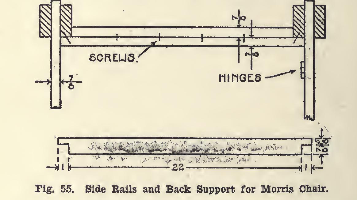
The stick which supports the back (Fig. 55, lower part) should be three-quarters, by one and one-half, by twenty-four inches. The gauge is set to seven-eighths of an inch, and the ends gauged to line squared around at a distance of one inch from each end, the block being held against what is to become the under side of the stock. Saw as indicated in Fig. 55, lower part.
The brackets which support the arms (Fig.
53) are made by squaring up a piece two inches, by two and three-quarter inches, by five inches, and ripping this diagonally. The roughness made by the saw is planed off.
All parts should be well scraped and sand papered, preparatory to putting together. If mill-planed stock is used, the mill marks must be planed off before sandpapering.
Begin by placing the front rail in place; then the back rail. Pin the tenons to the mortises by using three-eighths-inch dowels, as shown in Fig. 53. Use clamps to hold the legs up snug to the shoulders while boring. If desired, the dowels need not show on the front. Bore from the rear, not quite through the legs.
Fasten the side rails together as shown in Fig. 55, upper part; then fasten them to the legs as shown in the same figure. The place at which to fasten them to the legs may be determined by using one of the three upright side bars as a measure, measuring down from the shoulder of the tenon which is on the top of each leg.
Mark and dowel, as shown in Fig. 53, for the uprights. A three-eighths-inch dowel may be used. Great care will be required in laying off the dowel-holes, for, if they are not just right, trouble will be experienced in clamping the side together.
Place the arm in place, and clamp the side together after having glued and placed the uprights in position.
The arms are to be fastened to the legs by three-eighths-inch dowels, the holes being bored from the inner edge of the arm through the tenon (Fig. 53).
Place the brackets which support the arms. They may be nailed, and the heads set and put tied; or they may be blind-doweled and glued.
The framework of the back is put together by means of screws. Bore, and countersink from the back side, two screws placed diagonally be ing sufficient for each joint. Place the cross pieces so that there shall be twelve inches from inside to inside of the supports.
Fasten the back to the main frame of the chair, as shown in Fig. 53, by means of common iron strap-hinges.
The seat may be made by placing slats from side to side, the ends of which shall rest on the ledge made by the side rails. A better way would be to upholster the seat, putting in springs.
The bottoms of the legs are to be cut on an angle. Measure up one inch on each of the rear legs, and lay a straight-edge so as to connect this point with the bottom of the front leg.
This gives the slope. Square across each leg, and connect on the other side, and saw.
Place casters under the legs, and the chair is ready for the finish.
A satisfactory effect may be obtained by using one of the mission oak stains now so com mon on the market, following the directions of the manufacturers.
Cushions suitable can be bought ready-made, either in leather or cloth, and of a size to fit.