A Plant Stand or Pedestal
piece, lines, top, pieces, set, inches, screw, middle, thickness and inch
There should be bored into each end of this upright, when it has been completely squared up, a hole three-sixteenths of an inch in diam eter, and one and three-quarters inches deep. This hole will take in the body of a one-quarter by three-inch lag screw, without the threads. If any other size screw is used, the size of the hole must be changed to correspond.
Square the two pieces for the base to one and three-quarters by one and three-quarters by twenty inches.
Place these pieces side by side in the vise with their ends evened and one set of face marks against the vise jaws. From each end, measure four inches and bore one-inch holes. Place the spurs of the bit in the crack between the two pieces; this will form a half-circle on each piece. Set the gauge to one-half inch, and connect these half-circles on each side of each piece. With compass or turning saw, saw along the lines far enough to allow the rip saw to enter; then finish sawing with this. Saw from one side of the piece a while; then reverse, and saw from the other side, repeating the change frequently as the sawing proceeds.
On the sides, at the ends (Fig. 112) describe arcs of circles, using a three-quarter-inch radius. Round off the ends, using chisel and plane or spokeshave.
Next lay out the joint. This joint is called a "half-lap" or "halved cross;" and if the direc tions are carefully followed, no trouble ought to be experienced in securing a proper fit.

First, locate the middle, and square a light knife line across both pieces at this point. To make sure the middle has been found correctly, turn one of the pieces end for end, and place it alongside the other. If the middle lines still correspond when the ends are evened, the lines are properly located. If they do not, the mid dle lies at a point midway between the two lines, and a line should be drawn across the two pieces at this new point.
Second, measure to each side of these middle lines half the width of the pieces, and make points with the knife blade. Before squaring lines across, however, place each piece upon the other, to see that these points are exactly located.
Third, square the lines across the top and down the sides of one piece, but across the bot tom and up the sides of the other.
Fourth, set the gauge for one-half the thick ness of the pieces at the joint, and gauge on each side of each piece, between the knife lines. Keep the gauge-block against the top surfaces of each piece. A little thought will make clear the importance of this direction. If the gauge spur could be set at exactly half the thickness, and the two pieces were of exactly the same thickness, the gauging might be done from top or bottom surfaces. This condition seldom exists. Suppose, then, that the spur should happen to be set to mark out a depth of more than one-half the thickness of the piece. In that case, the surface of one piece would sink below that of the other when the parts were put to gether. But, even though the spur were so set, if the block should be held so as to mark the depth on one piece, and the thickness of the part remaining on the other—that is, if the gauging should be done from the top surfaces of each these surfaces would be flush, though the depth of opening in one was more than in the other.
Fifth, saw accurately to the knife lines, keep ing the kerf entirely upon the waste wood.
Sixth, chisel carefully to the gauge-lines; work from each side of the piece when nearing the lines.
Seventh, fit the parts together. This requires care. If the fit is forced, the pressure on the sides of the groove will cause one member to be bowed up and the other down, so that the piece will rest on but two of its four feet. On the other hand, the parts must not be so loosely fitted that they will leave unseemly openings at the joints. It ought to be so that the parts can be put together with just a slight pressure of the hands.
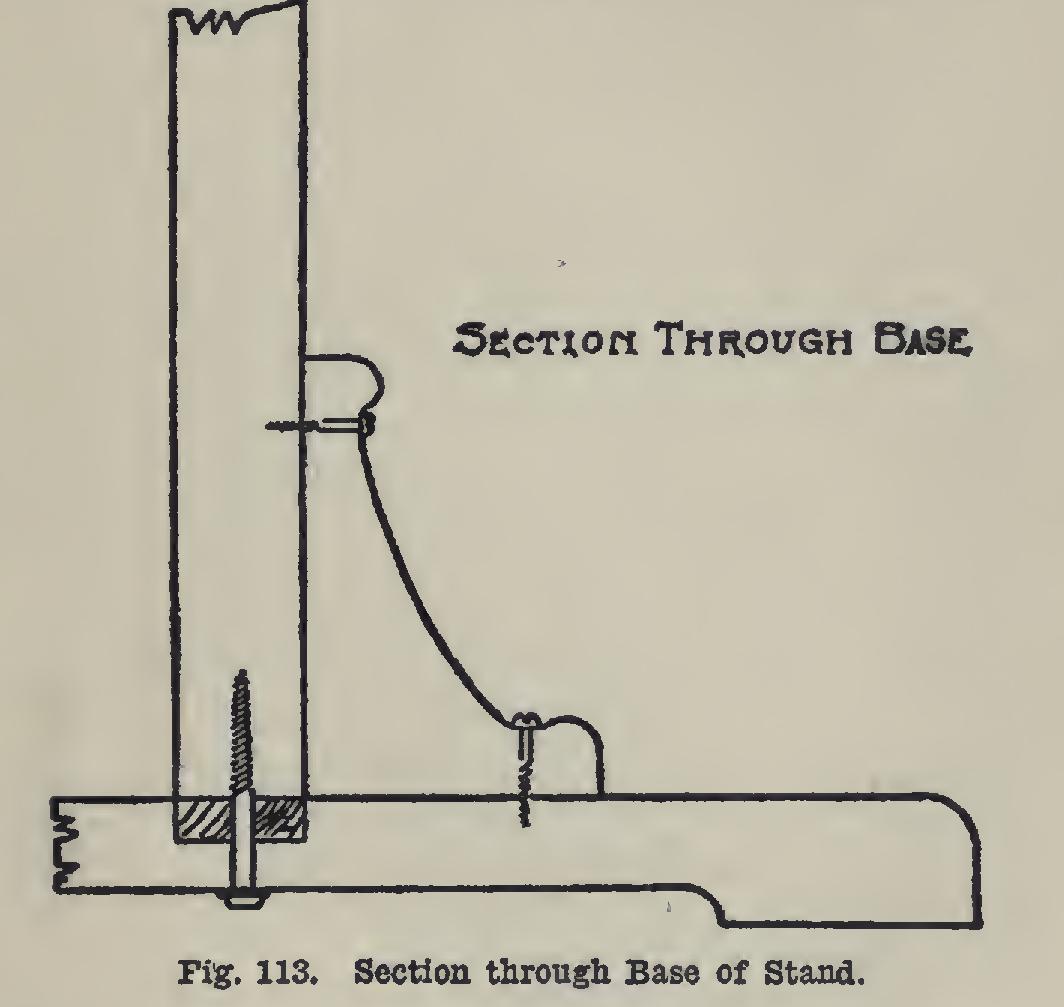
The four braces may next be laid out and sawed. It is a good plan so to place the pattern or templet that the grain of the wood may run diagonally to the sides. A paper pattern will do. The sides are respectively four and six inches, and must be square one with the other and with the face sides. The curve is to be drawn freehand upon the templet. A turning saw will be needed to cut the curves; and a cab inet scraper, well sharpened, for smoothing them: The saw should be made to cut close to the line, so that the smoothing may not be made any more laborious than is necessary. These braces are to be fastened to the upright and the base with round-head blued screws. Holes three-sixteenths of an inch in diameter should be bored as indicated in Fig. 113.
Thoroughly scrape and sandpaper the differ ent parts, and stain and fill before putting them together.
In assembling, the parts of the base may be fitted, and the upright fastened to it by means of the lag screw. The braces may next be fas tened. The piece which is placed under the top is to be fastened to the post with a lag screw.
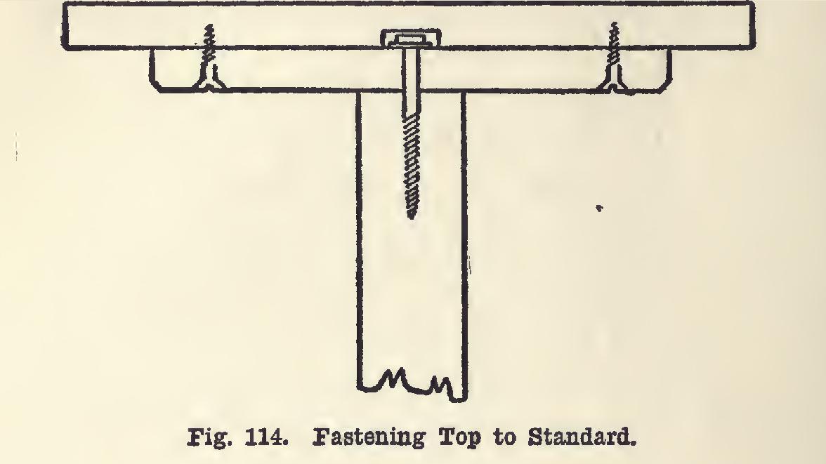
Three or four stout nails should also be driven through it into the post to prevent its turning it shrink so as partially to loosen the hold of the screw; or, better, mortise the top end of the post into this piece one-quarter of an inch deep. The top is next fastened to this piece by four or more screws, as shown in Fig. 114.
A
picture of a second piece of furniture is shown in Plate 24. This can be used as a hall tree, and will be found very convenient for use on the first floor of the home as a place to hang wraps. It makes an excellent addition to the bedroom furniture also.
The base is made in the same manner, and is of the same size as that of the pedestal. The upright is of the same thickness and width, but with a length of sixty-eight inches. A forty five-degree slope at the top adds seven-eighths of an inch more to this length.
The slope at the top is made by squaring a light pencil line entirely around the four sides at a point sixty-eight inches from the bottom, laying off on two opposite sides angles of forty five degrees. Saw and plane these slopes—the end will then be like the gabled roof of a house. Connect the middle of the ridge with each of the four corners by pencil lines.
The hooks may be placed as fancy dictates. The picture shows one way.