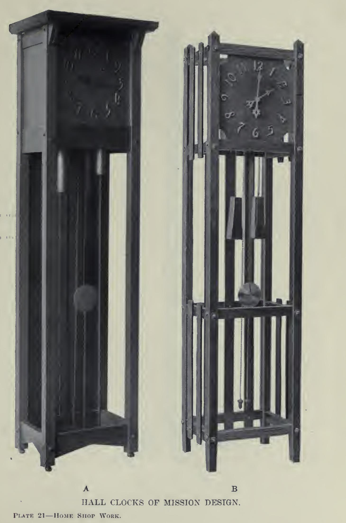
Hanging Clock of Mission Design
pieces, inches, inch, fig, knife, tenons, gauge, set, lines and mark
Place the two short posts (Fig. 100) together, with the inside surfaces upward. Even the top ends, and mark off one and five-eighths inches, one and one-fourth inches, fifteen and one-half, one and one-fourth, four and one-half, and one and one-fourth inches. There should remain one and one-eighth inches.
Place the back surfaces of these posts up ward; even the top ends; and mark off and square light pencil lines across, one and one eighth inches, one and one-fourth, two and nine sixteenths, five-eighths, thirteen and three eighths, five-eighths, two and nine-sixteenths, and one and one-fourth inches.
These pencil lines locate the ends of the various mortises. All of the pieces were pen ciled before any gauging was done, so that the gauging might all be done at once. But two set tings of the gauge are necessary. More are a waste of time. To set the gauge, find and mark with the knife point the middle of one of the pieces. Measure to each side of this mark three sixteenths of an inch. Set the gauge on the piece so that the block is against a face, and the spur on one of the knife marks. Tighten the set screw, and gauge for all mortises on all posts with this setting. The second setting is obtained from the first post by placing the block as was first done, placing the spur in the second knife mark. These mortises are to be three-eighths of an inch wide and nine-sixteenths deep. The gauge-block, in all gauging, must be held against an X X surface at all times. If the pieces are of the correct width and thickness, the first setting will be nine-sixteenths of an inch, and the second fifteen-sixteenths.
A three-eighths-inch chisel should be used in cutting these mortises, care being taken not to mar the ends or sides. No boring is necessary.
Fig. 101 (upper part) gives the layout for the tenons of the cross-bars. Even the ends of the five pieces after having placed them on edge, side by side. Measure, and mark with a knife a point one-half an inch from the evened ends; then, from this point, fourteen inches. Square knife lines across the edges of all these pieces at these two points. Separate them, and carry the knife lines around the other smoothed surfaces. These lines mark the shoulders of the tenons.

The gauging for the sides of the tenons is as follows: Set the gauge to one-quarter of an inch, and gauge on ends, on surfaces, and on edges, as far back as the knife lines, keeping the gauge-block against a joint-edge or a working face. Next set it to five-eighths of an inch, and gauge from the working face only. Again, set the gauge to one and one-half inches, and finish, this time with the block against the joint-edge.
The shoulders for the side-bars (Fig. 101, lower part) should be laid out before any gaug ing is done, so that these pieces may be gauged at the same time as those for the cross-bars, for their tenons are of the same size. The dis tance between the shoulders is eight and one half inches. There will be four of these pieces.
The tenons of the four pieces (Fig. 102, upper part) differ from those of the side-bars in width only. The second setting of the gauge, when the block is held against the joint-edge, is seven eighths of an inch, instead of one and one-half inches.
There are three pieces shown in Fig. 102; and
the distance between the shoulders is four inches, the tenons being one-quarter of an inch long. As the tenons of the six long pieces (Fig. 102) are of the same size as those of the short pieces, their shoulders should be marked before beginning any gauging on the short pieces. The distance between the shoulders will be twelve and seven-eighths inches. The gauge is set first to three-sixteenths of an inch, and all the pieces gauged from both joint-edge and working face. It is then set to nine-sixteenths of an inch.
The mortises (Fig. 101, upper part) are to be cut in two of the pieces only. They are laid off from the middle toward each end. Measure three-sixteenths each side of the middle, and mark with knife point; then two and three eighths and three-eighths. Square knife lines across the two pieces at once.
The mortises (Fig. 102) should be laid off now—three-sixteenths each side the middle, one and one-eighth inches, then three-eighths. The gauging for the cross-bars and side-bars may be done at the same time. The first setting will be one-quarter of an inch, the second five-eighths, as for the tenons on these pieces. The mortises are to be cut a little deeper than one-quarter of an inch.
Clean all pieces with scraper and sandpaper, and glue up the back and front. When these parts have remained in the clamps long enough for the glue to harden, put in the side-bars.
The slats (Fig. 99) should be put on before the side bars are put in, however. They are spaced two inches apart, and may be fastened with light brads at the middle of the piece, and these covered with ornamental wrought nails. Blued screws may be used.
The braces have one end of each cut to an angle of forty-five degrees. They are then held in place (Fig. 99), and the length marked. They are fastened in place with screws put through from the back so that they will not show from the front.
In the clock shown, lag screws, one-quarter by three inches, were put through the posts into the center of the tenons of each one and three quarters-inch bar. Washers were used, and the effect was quite pleasing. The posts should be bored with a one-quarter-inch bit, the tenons with a three-sixteenths to the depth the screw will enter.
The face may be fitted in place. It is better to fit a side and an end, then marking with a knife while holding it in place, than to square to dimensions. The corners are cut, a two-inch circle being described from each corner as a cen ter. The figures should not be placed upon the face until it has been stained. They are a part of the movement and will be put on by the one who sets the movement. The dotted lines (Fig. 99) show the shape of the box which is to hold the clock works. The size of it will depend upon the kind of movement, but sides should be made so that they can be fastened with screws to the cross-bars. The back should be put on with screws.
The face should have metal buttons fastened at top and bottom on the back, to turn over the cross-bars to keep the face from falling forward, and to permit of its easy removal.
A medium-dark mission stain, followed when dry by a very thin coat of shellac, will be suitable.