Ad Ab
line, fig, section, draw, lines, cut and straight
The curved portions of the side rafters are made separate from the straight part and are most generally formed of two thicknesses of inch stuff, first sawed the right shape and nailed together, and then spiked to the straight part of the rafter. When so much of the roof has been put up, it will be as well to mark on the end of the floor joists the proper depth for the gutter. This will be best done by holding a straight-edge on the ends of the joists, with incline sufficiently to allow water to run off, and marking on each joist the depth it will require to be cut down.

The vertical part of the gutter is cut down in a line with the lower ends of the side rafters. The cornice brackets, which are cut cf a shape suit able for receiving the different parts of the cor nice, are made of inch stuff and are nailed to the floor joists, as shown by the dotted lines and nail marks at dk. The best method to pursue in put ting them up is to first nail one on to the joist at either extremity of the roof, then stretch a line tight between the same points on each, and nail up the intervening brackets, with the same points touching the line. If the line is tightly stretched and proper care is taken in nailing up the brackets the cornice will be perfectly straight.
In Fig. 155 we have a section of a similar roof with straight sides. The different parts are lighter than those of Fig. 154, and the construc tion is adapted for a balloon frame building. The letters in Fig. 155 denote the same parts as the same letters in Fig. 154, and the explanation of Fig. 154 will answer for Fig. 155 so far as the same letters are concerned. Pc is the balloon frame studding; c, a longitudinal piece for the floor joists to rest upon. The studs are cut out at the top to receive the piece c, and will thus prevent the frame from spreading.
Since there is no curve on the rafter, the face of it comes flush with the inside of the gutter. Hence the side rafters are cut out at the heel to rest on the piece h, instead of the toe, as in Fig. 154, The piece h is beveled in order that the thrust on the side rafters shall not throw the lower ends out. The inside of the gutter is also made inclining so as to give as much substance as possible between the gutter and the piece h. The remaining parts are the same as those in Fig. 154, and the same description of those parts
will answer for both cuts.
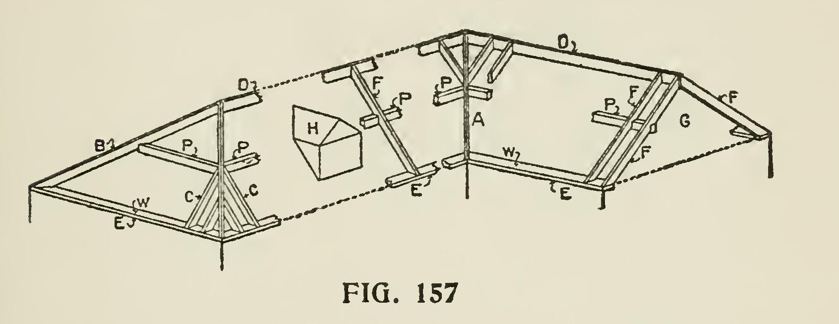
Fig. 156 shows how to find the angle=rafter and angle=cornice bracket, when the section as above described has been drawn. Let ABc repre sent the given section on the drafting board or floor. Draw the line AO at an angle of 45 degrees with AF. Then from any points C, P, 0, etc., of the section as shown, draw lines perpendicular to AF, and intersecting AO.
In order to transfer the distances AE, AP, etc., on AO to All, it is most convenient, in our small illustration, to describe arcs with A as a center; but in practice, since the distance AO will be several feet, it will be best to lay a straight edge along the line AO, and mark the points A, E, P, etc., on it; then change the position of the straight edge and lay it along All, the point before on A being made to coincide with it again, and transfer the marks to the floor or board on the line All at E', P", etc. When this has been done, draw lines from these marks and perpendicular to All. Now draw lines from the points C, P, 0, etc., on the section ABC, but parallel to Fil, and inter secting the lines which are perpendicular to All. Note the interesection of any two of these lines which are produced from the same point of the section, and this intersection will be the similar point of the angle-rafter. Perhaps the subject will be better understood if we follow the details of finding a single point of the angle-rafter; such for instance, as that corresponding to the point P of the given section. From P draw PP' perpen dicular to AF, and intersecting AO at P'. Make the distance AP" on All equal to AP' on A0, either by describing an arc with A as a center and AP' as a radius, or by transferring the point P' to P" on a straight-edge, as before stated. From P" draw P" P" ' perpendicular to AII. Then from P on the section draw a line PP" ' parallel to FH, until it intersects the line P" P" ' in the point P" '. This point P" ' will be the point of the angle-rafter corresponding to the point P of the section. After finding all the points in a similar manner, they must be joined by the requisite curved line, and a pattern rafter cut to fit. It will be apparent from inspection that the angle bracket is found in the same manner.