Ad Ab
roof, draw, piece, parallel, equal, rafters and rafter
AB, AD in e and f. Make gk equal to gh, and join ke, kf ; and the angle ekf is the angle of the backing of the hip rafter C.
Fig. 150 shows the method of obtaining the backing of the hip where the plan is not right angled.
Bisect AD in a, and from a describe the semi circle, AbD ; draw ab parallel to the sides AB, DC, and join Ab, Db, for the seat of the hip rafters. From b set off on bA, bD, the lengths bd, be, equal to the height of the roof bc, and join Ae, Dd, for the lengths of the hip rafters. To find the backing of the rafter: In Ae, take any point k, and draw kh perpendicular to Ae. Through h draw fhg perpendicular to Ab, meet ing AB, AD, in f and g. Make hl equal to hk, and join fl gl ; then fl, gl is the backing of the hip.

Fig. 151 shows how to find the shoulder pur= lins: First, where the purlin has one of its faces in the plane of the roof, as at E. From c as a center, with any radius, describe the arc dg ; and from the opposite extremities of the diameter draw dh, gm, perpendicular to BC. From e and f, where the upper, adjacent sides of the purlin produced cut the curve, draw ei, fl parallel to dh, gm; also draw ck parallel to dh. From 1 and i draw Im and ih parallel to BC, and join kh, km. Then ckm is the down bevel of the purlin and ckh is its side bevel.
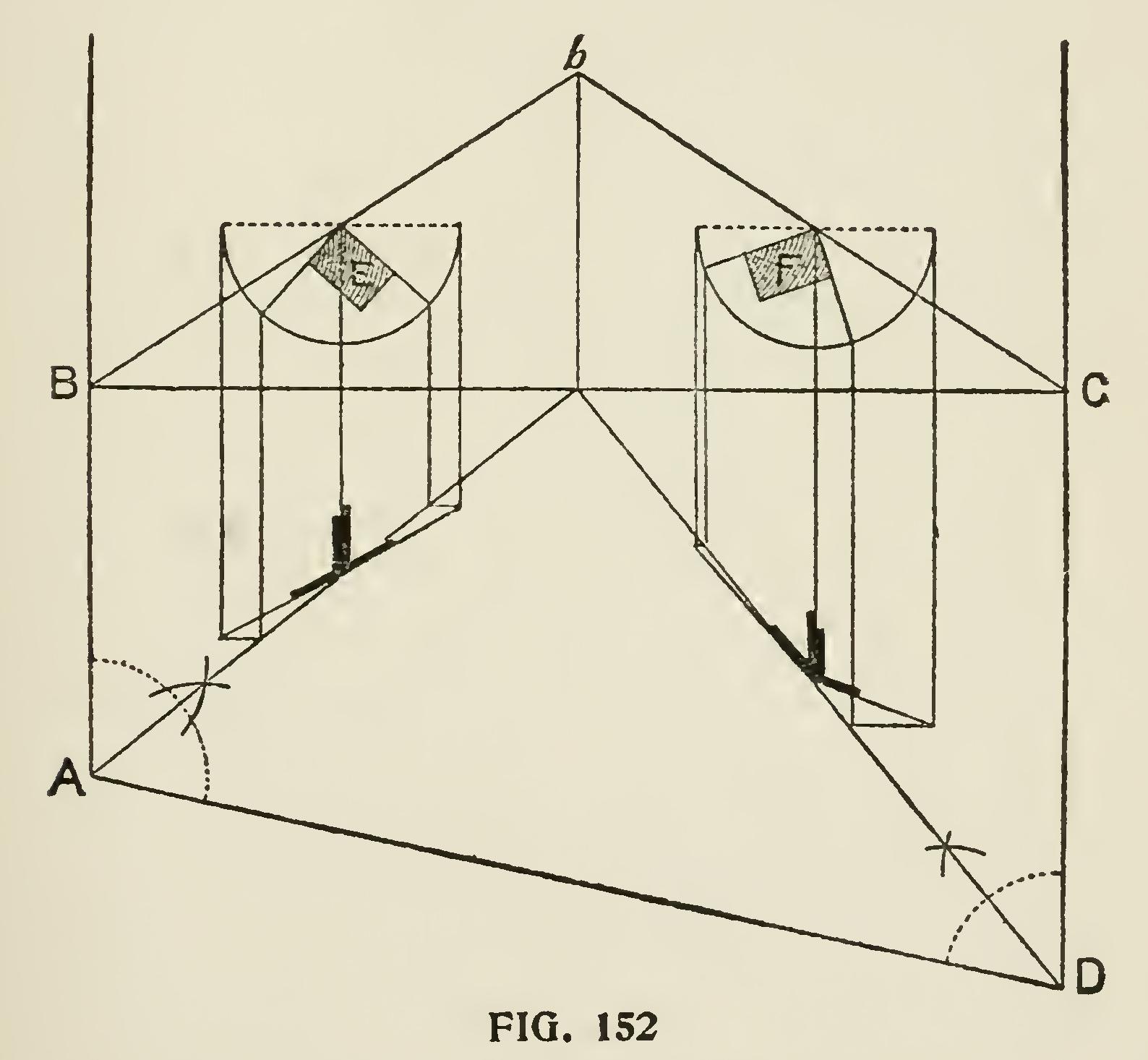
When the purlin has two of its sides parallel to the horizon, it is worked out as shown at F. It requires no further explanation.
When the sides of the purlin make various angles with the horizon, Fig. 152 shows the appli cation of the method.
It sometimes happens, particularly in rail road buildings, that the carpenter is called upon to pierce a circular or conical roof with a saddle roof, and to accomplish this economically is often the result of much labor and perplexity if a cor rect method is not at hand.
The following method, shown in Fig. 153, is an excellent one and will, no doubt, be found useful in cases such as mentioned : Let DH, FM he the common rafters of the conical roof, and KL, IL the common rafters of the smaller roof—both of the same pitch. On Gil set up Ge equal to ML, the height of the lesser roof, and draw ed parallel to DF, and from d draw cd perpendicular to DF. The triangle Ddc will then, by construction, be equal to the triangle ELM, and will give the seat and the length and pitch of the common rafter of the smaller roof B. Divide the lines of the seats in
both figures, Dc, KM, into the same number of equal parts; and through the points of division in E, from G as center, describe the curves ca, 2g, if, and through those in B draw the lines 3f, 4g, Ma, parallel to the sides of the roof and inter sectiog the curves in fga. Through these points trace the curves Cfga, Alga, which give the lines of interesction of the two roofs. Then to find the valley rafters, join Ca, Aa; and on a erect the lines ab, ab perpendicular to Ca and Aa, and make them respectively equal to ML ; then Cb, Ab is the length of the valley rafter.
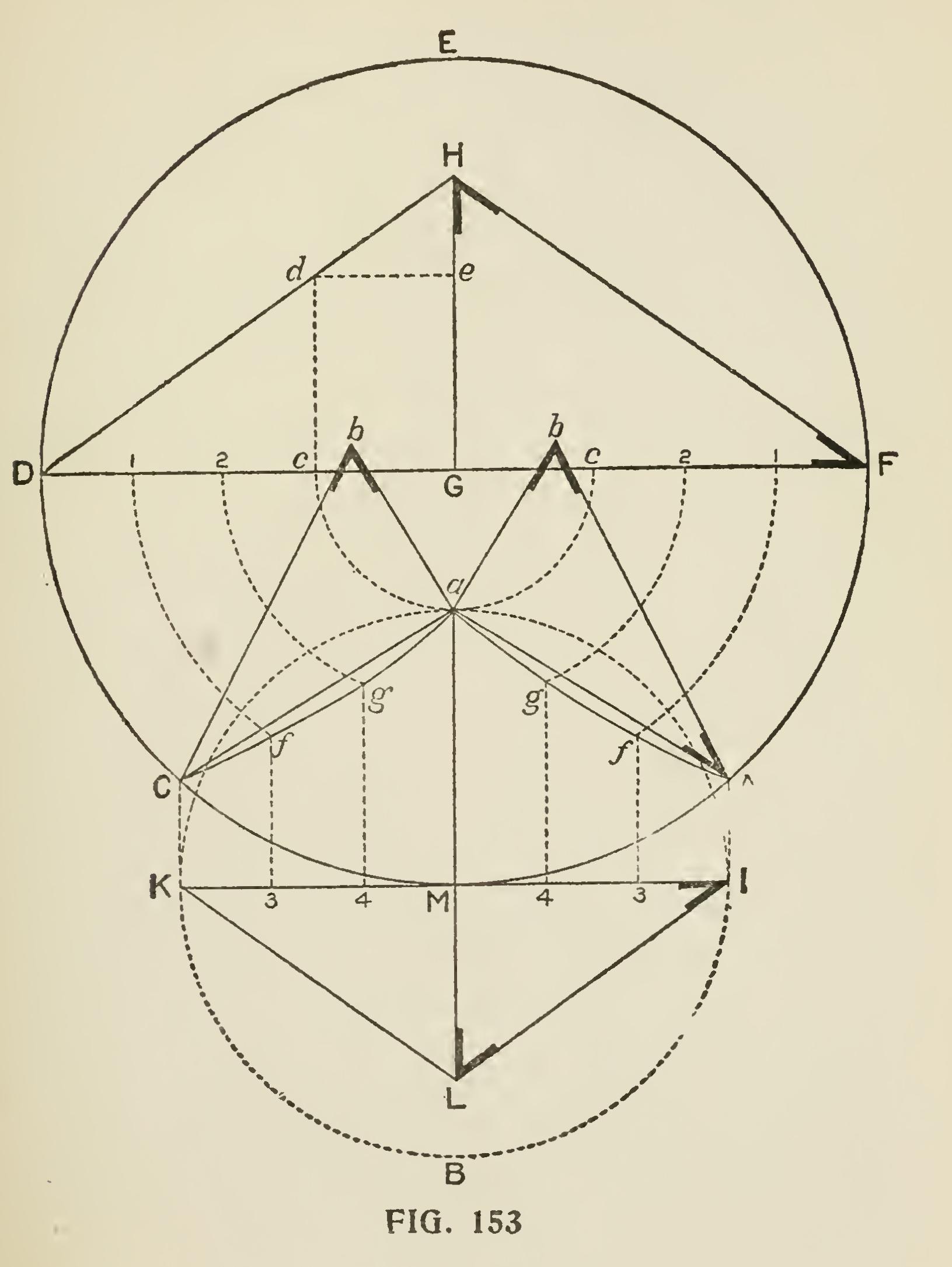
Fig. 154 shows a section of a mansard roof with concave sides, and the manner of framing the same when it is to be erected on a brick or stone building. Pc is the wall ; c the wall plate; AB the floor joist ; hi is the side rafter ; aie the ceil ing joist ; ao the top rafter; Bbd the bracket to nail cornice to; b the gutter, and ri the studding, which will be required if it is desirable to finish the roof story for sleeping rooms.
The wall plate is made of two thicknesses of two-inch plank nailed together and lap-jointed at the ends. The joints should receive the longi tudinal piece h, and the ends of each should be sawed off square at or near the dotted line k. They should then be put into place, nailed to the wall plate, and the piece h should be firmly nailed to each. The lower end of the side rafters is cut out at the toe to rest on the piece h. The upper ends are also cut to receive the piece i, to which they should be firmly nailed.
If it is required to lath and plaster on the ceiling joists, they should be notched to rest on the piece i; but if the room is to remain rough, it will be as well to nail beveled pieces on each, as shown by the dotted line at s. The end of each ceiling joist should be sawed in shape to receive the moulding a, with which it is usual to finish the upper part of the roof. The top rafters may rest either on a longitudinal piece laid on the ceiling joists or on the piece i—the latter being the better method.