Mouldings
lines, line, db, fig, moulding, draw, horizontal and ba
Fig. 177 is the Scotia. This is the hollow moulding, sometimes consisting of a semicircle only : viz., the reverse of the torus. In other instances as in Fig. 177, it is composed of two quadrants; and in others it is drawn from three centers, as in Fig. 178. To draw this, divide the depth of the moulding into three equal parts, and with one-third describe the quadrant r u ; produce the horizontal r u, and from r set off i, equal to half u r. At n erect a perpendicular, and mark on it n k, equal to i u; draw i k, and bisect it; produce the bisecting line until it cuts n k in s. Draw s i and produce it. From i, with radius i u, draw the next portion of the curve, meeting s i produced; then complete the curve by an arc drawn from s with radius s n.
A fillet
is the small flat edging used to separate two larger mouldings, to strengthen their edges, or to form a cap or crowning to a moulding. The fillet is one of the smallest members used in cor nices, architraves, bases, and pedestals. When placed against the flat surface of a pedestal, it is usually joined to it by a small quarter-round hollow called the Apophyge (Fig. 179).
The torus, when worked very small, is called the Astragal (Fig. 180) ; but when worked so as not to project, as on the edge of boards to be joined, it is called a bead.
Mitering Moudings.
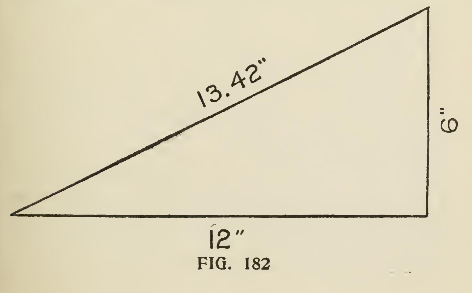
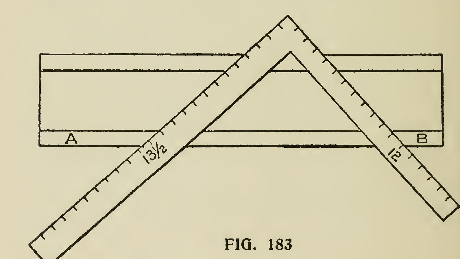
One of the most troublesome things the car penter meets with is the cutting of a spring mould ing when the horizontal portion has to mitre with a gable or raking moulding. Undoubtedly the best way to make good work of these mouldings is to use a mitre box. To do this make the down cuts, B,B (Fig. 181), the same pitch as the plumb cut on the rake. The over cuts 0,0,0,0 should be obtained as follows : Suppose the roof to be a quarter pitch—though the rule works for any pitch when followed as here laid down—we set up one foot of the rafter, as at Fig. 182, raising it up 6 inches, which gives it an inclination of quarter pitch; then the diagonal will be nearly 13/ inches. Now draw a right-angled triangle whose two sides forming the right angle, measure respectively 12 and 13/ inches, as shown in Fig. 183.
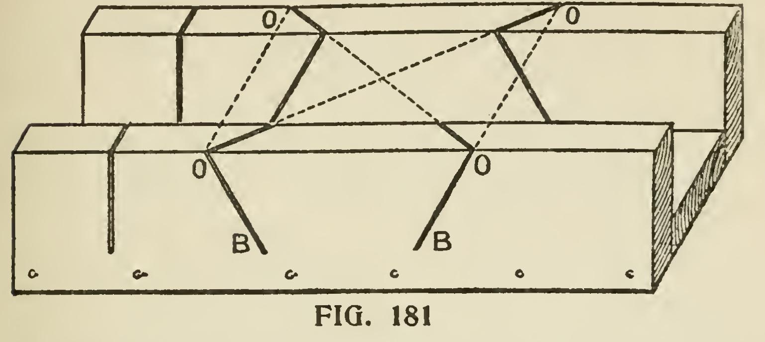
The lines A and B show the top of the mitre box with the lines marked on. The side marked 13/ inches is the side to mark from; this must be borne in mind, and it must be remembered that this bevel must be used for both cuts, the 12-inch side not being used at all.
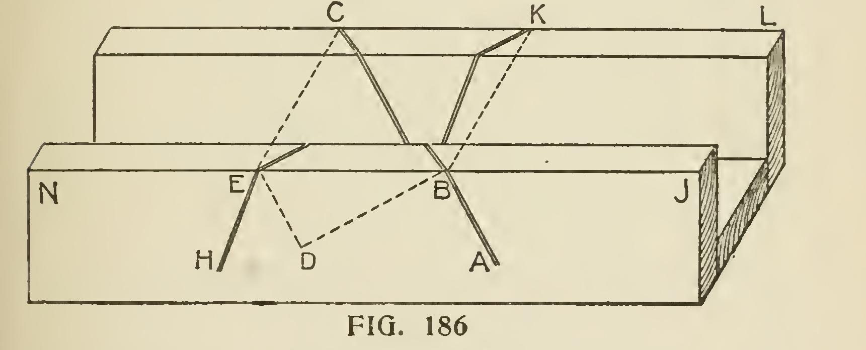
Another excellent method for obtaining the section of a raking mould that will intersect a given horizontal moulding, is given below, also a manner of finding the cuts for a miter box for same.
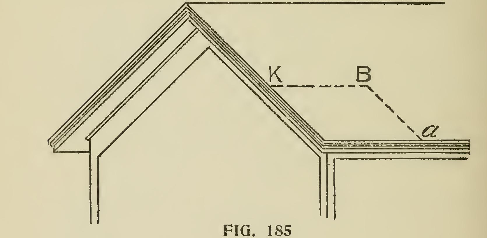
The principles on which the method is based being, first, that similar points on the rake and horizontal parts of a cornice are equally distant from vertical planes represented by the walls of a building ; and, second, that such similar points are equally distant from the plane of the roof. Representing the wall faces of a building by the line DB (Fig 184), and a section of the horizontal cornice by DBabcdef Bab being the angle of the roof pitch, draw line aa', cc', ff', parallel to DB and intersecting the line ka', which is drawn at right angles to DB through the point B ; then, with B as a center, describe the arcs a'k, c'1', etc., intersecting the same line ka' on the opposite side of DB. This gives the point k at the same distance from DB as the points a and a', and the line 11' at the same distance as cc'. The rest of the same group of parallel lines are found to be similarly situated with respect to DB.
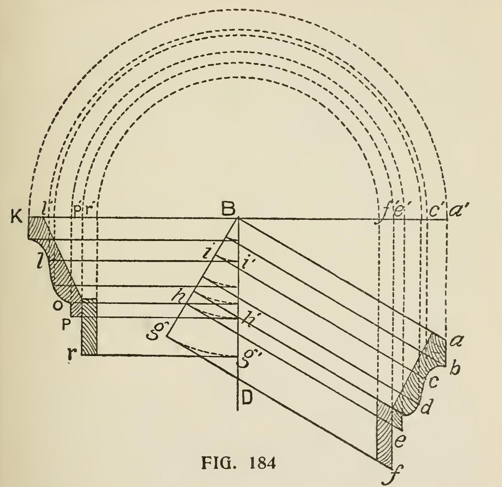
From Descriptive Geometry we have the prin ciple, that if we have given two intersecting lines contained in a plane, we know the position of that plane, hence we may represent the plane of a roof by the line Ba and Bk (Figs. 1S4 and 185) ; and since it will be most convenient to measure the distances required in a direction perpendicular to that plane, in following out the principle draw lines from the points cef, etc., parallel to Ba and intersecting the line Bg, which is made prpendicu lar to Ba. This gives us on Bg the perpendicular distance of the points cef, etc., from the line Ba. From the intersection of these lines with Bg, and with B as a center, describe arcs intersecting the line DB at i'h'g', etc. ; from these intersections with DB draw lines 1'l, h'p, g'r, etc., parallel to Bk, until they intersect the first group of lines drawn perpendicular to Bk, and the intersection of each set of two lines drawn from the same point on the horizontal section will give the similar point of the rake section. Taking the point 1, for example, we have, as before proved, 1 at the same distance from DB as c, and i being at the same distance from Ba as c, Bi being equal to Bi', and Bi' equal to 11', 11' is equal to Bi' ; and consequently 1 is the same dis tance from Ba, which is in accordance with prin ciple already shown. The intersection of each set of lines being found and marked by a point, the contour of the moulding may be sketched in, and the rake moulding, of which the section is thus found, will intersect the given horizontal moulding, if proper care has been taken in executing the diagram.