Mouldings
moulding, lines, line, draw, shown, fig, miter, circular, ab and shape
Fig. 186 shows how to find the miter cut for the rake moulding, the cut for the horizontal one being the same as for any ordinary moulding. Take an ordinary plain miter-box, NJL, and draw the line AB, making the angle ABJ equal to the pitch angle of the roof. Draw BD perpendicular to AB, and extend lines from B and E square across the box to K and C; join BC and EK. ABC will be the miter cut for two of the rake angles ; HEK will be the cut for the other two angles, the angle HEN being equal to the angle ABJ. In mitering, being horizontal and rake moulding, that part of the moulding which is vertical when in its place on the cornice, must be placed against the side of the box.
Lines for the cuts in a miter box,
for joining spring mouldings, may be obtained as follows : If we take BS (Fig. 187), the moulding showing the spring or lean of the member, and DE the miter required, then proceed as follows : 'With A as a center, and the radius AG, describe the semicircle FHGC ; then drop perpendiculars from the line FC, at the points F, A, H, G, and C, cutting the miter line as shown at the line ID. Draw IE parallel to FC, then from I draw IS, which will be the bevel for the side of the box, and the bevel CR will be the line across the top of the box. The miter line, as shown here, is for an octagon, but the system is applicable to any figure from a tri angle or rectangle to a polygon with any number of sides.
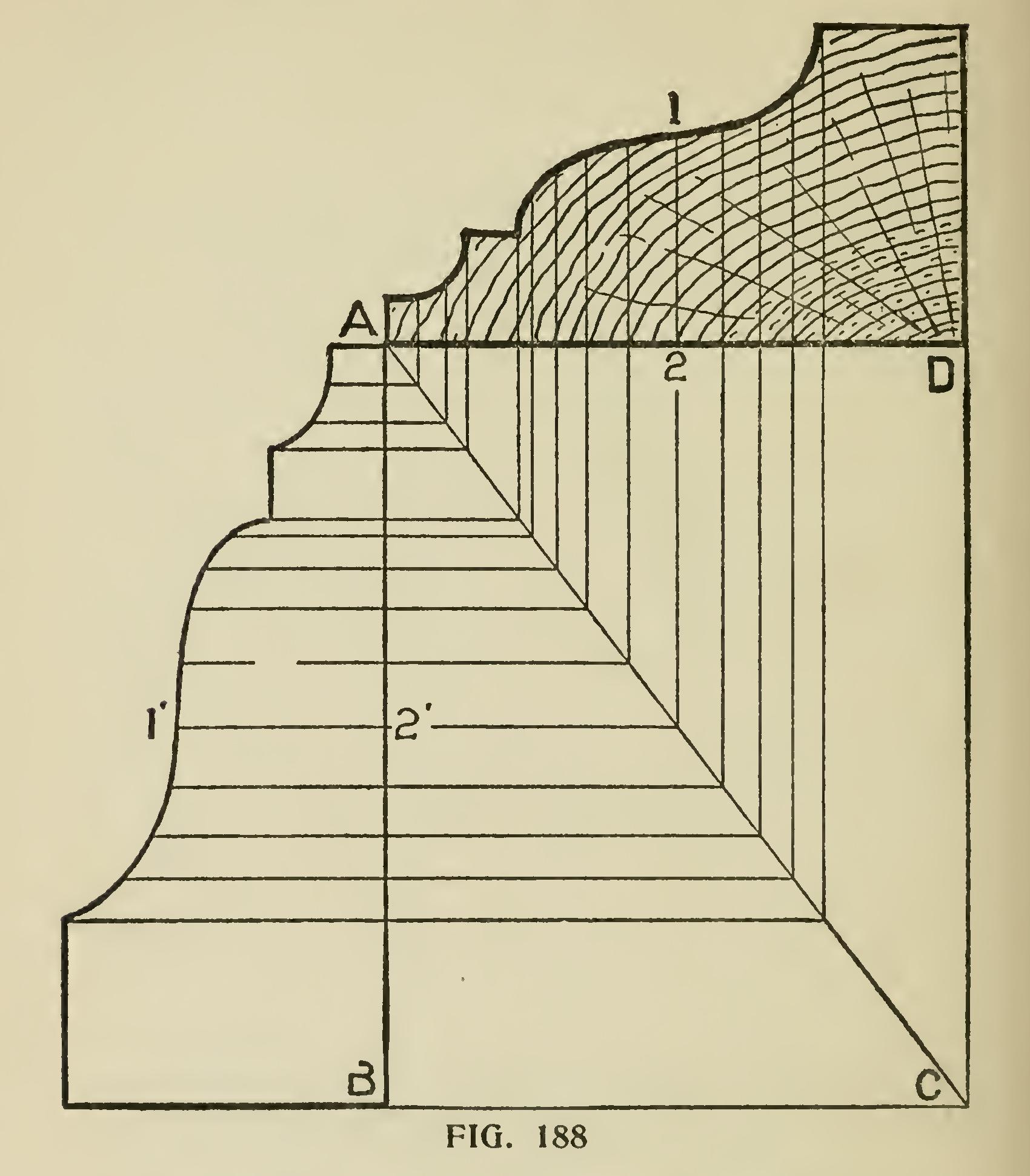
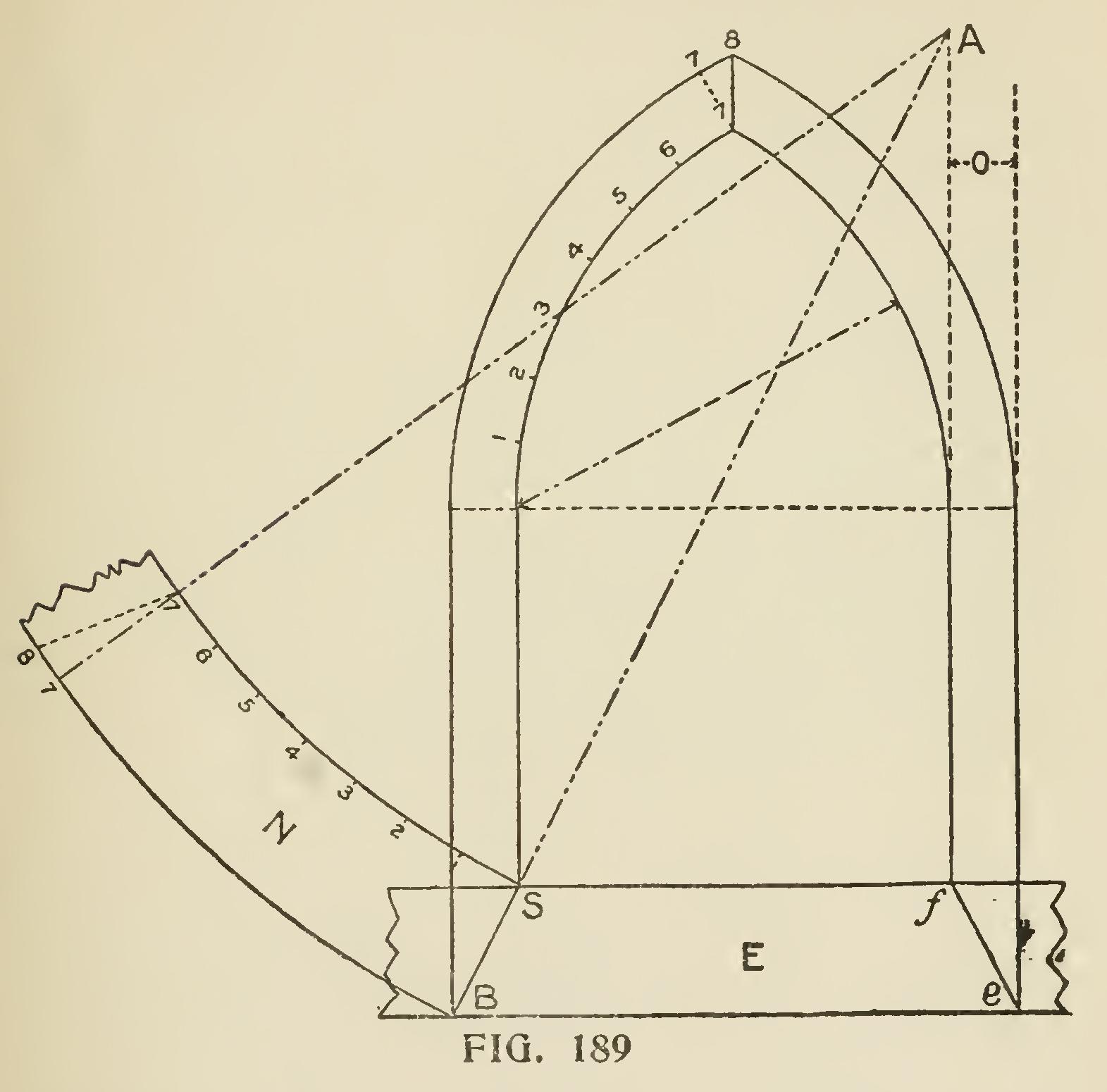
Fig. 188 shows the manner of finding propor tons of a small moulding which is required to miter with a larger one, or vice versa. Let AB be the width of the larger moulding, and AD the width of the smaller one; construct with these dimensions the parallelogram ABCD, and draw its diagonal AC. Let AB be the section of the moulding which we wish to reduce to member with a moulding the width of AD. Draw any number of parallel lines to BC cutting the line AC, from which points draw lines parallel to DC and beyond the line AD. From the latter set off the thickness of the mould ing on the corresponding lines as 1-2 will give the contour of the mould for the lesser width or vice To Obtain Correct Shape of a Veneer. Fig. 189 exhibits a method of obtaining the correct shape of a veneer for covering the splayed head of a gothic jamb. E shows the horizontal sill, of the splay, FA the line of the inside of jamb, o the difference between front and back edges of jamb, BA the line of splay. At the point of junction of the lines BA, FA, set one point of the compasses, and with the radius AB draw the outside curve of n; then with the radius AS draw the inside curve, and n will be the veneer required. This will give the required shape for either side of the head.

To get the contour or outline for a raking mould ing, proceed as shown in Fig. 190. The horizontal moulding is divided into any number of parts, equal or unequal, as shown at abcdefg. The line AC shows the rake or inclination. Draw lines parallel with AC, from a to D, b to v, etc. Drop a line AB, perpendicular to AC, at any convenient point on the rake, make the distance AC equal to ho ; then drop the lines pgrst, and where these lines cut the lines abcdefg, these points of contact will be in the curve line of the rake moulding, as at Dvwxyz. From these points trace the curve, which will be the proper shape for the moulding.
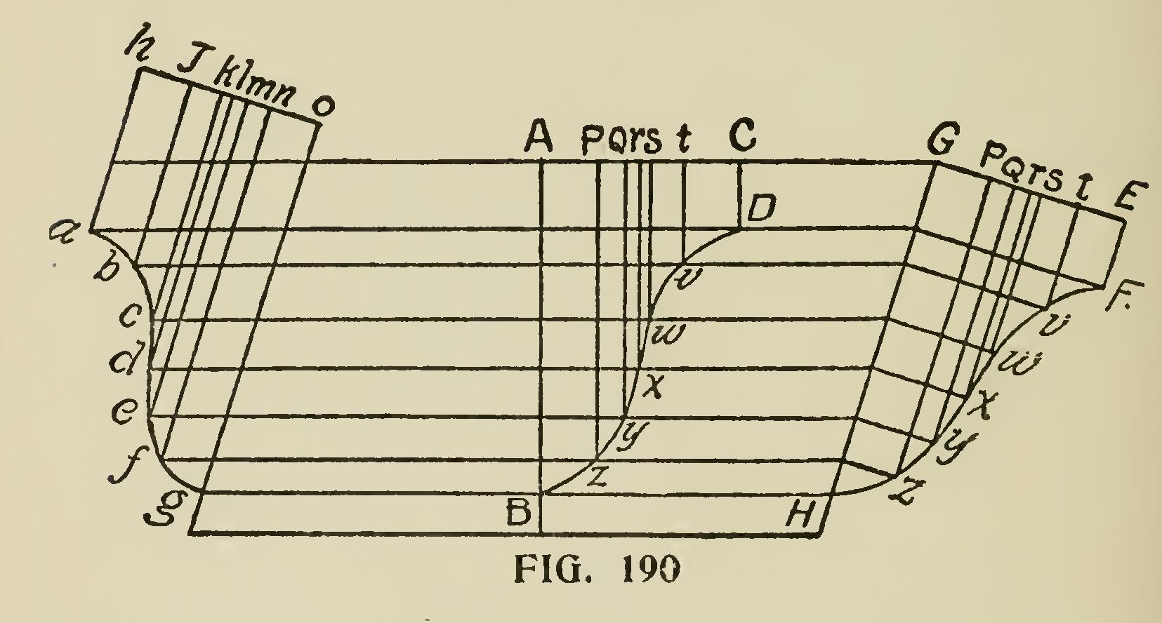
The divisions and lines shown at GHEF give the proper shape for the moulding at the top return.
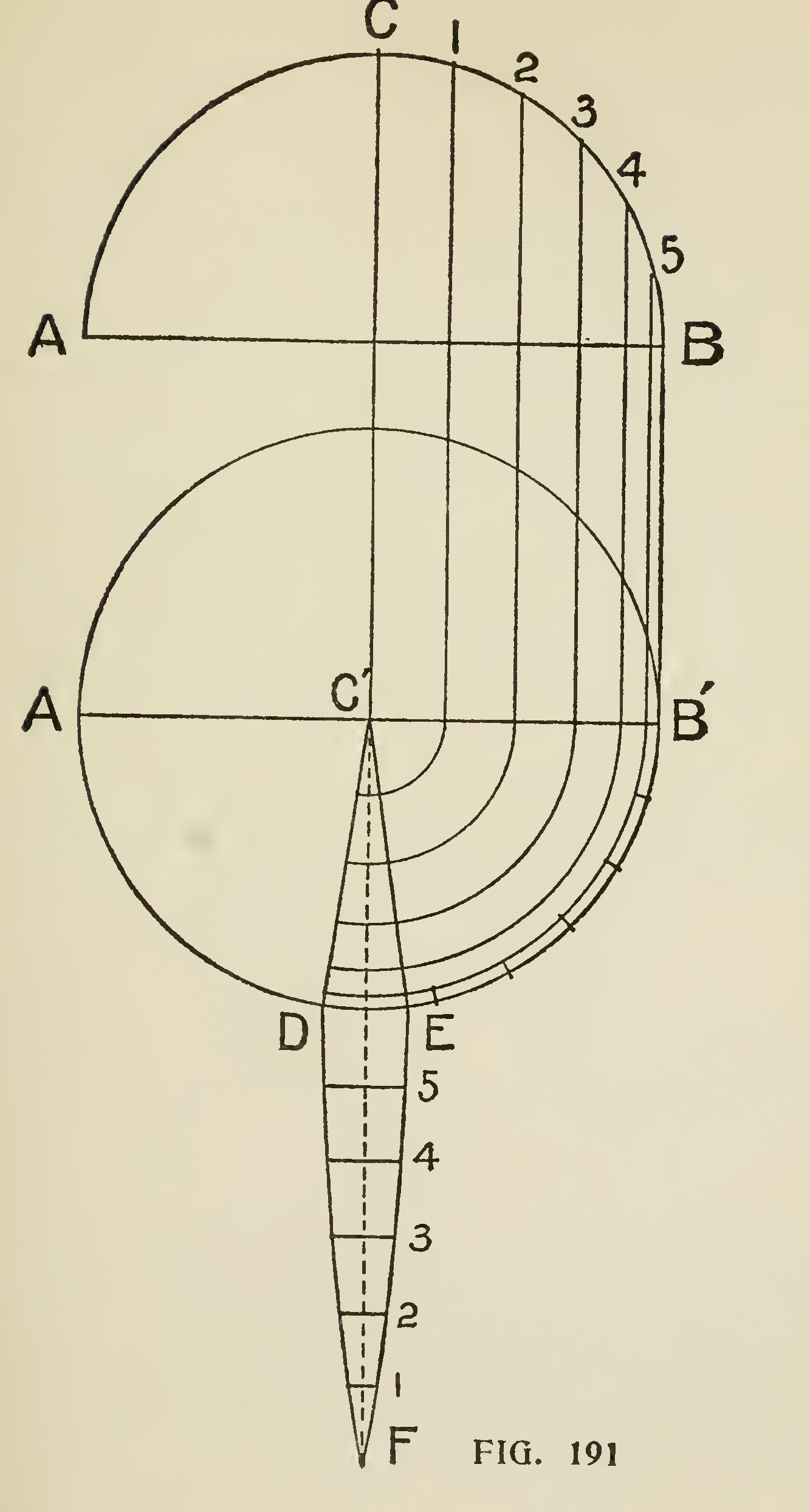
To Cover a Circular Dome with Vertical Board= ing. The upper part of Fig. 191 represents the elevation of the dome, and the lower part repre sents the plan and the shape of the board in the stretch-out. Divide the diameter of the dome into spaces equal the width of the boards to be used. Divide one side of the elevation into any number of equal parts, as 1, 2, 3, etc., and from these points draw parallel lines down to the diameter of the plan as at C"B". From C" as a center draw lines C"D" and C"E which represents the board in its respective place on the dome. From C" as center and with the points 1, 2, 3, etc., on the diameter swing around to C"D and C"E as shown; and on the line C"F lay off the distance 5, 4, 3, etc., which will be the correct length or stretch-put of the board. The length of the cross lines between C"D and C"E governs the length of the cross lines of the board. Care should be taken to not have the boards too wide, as the narrower the boards the better they will fit the dome.
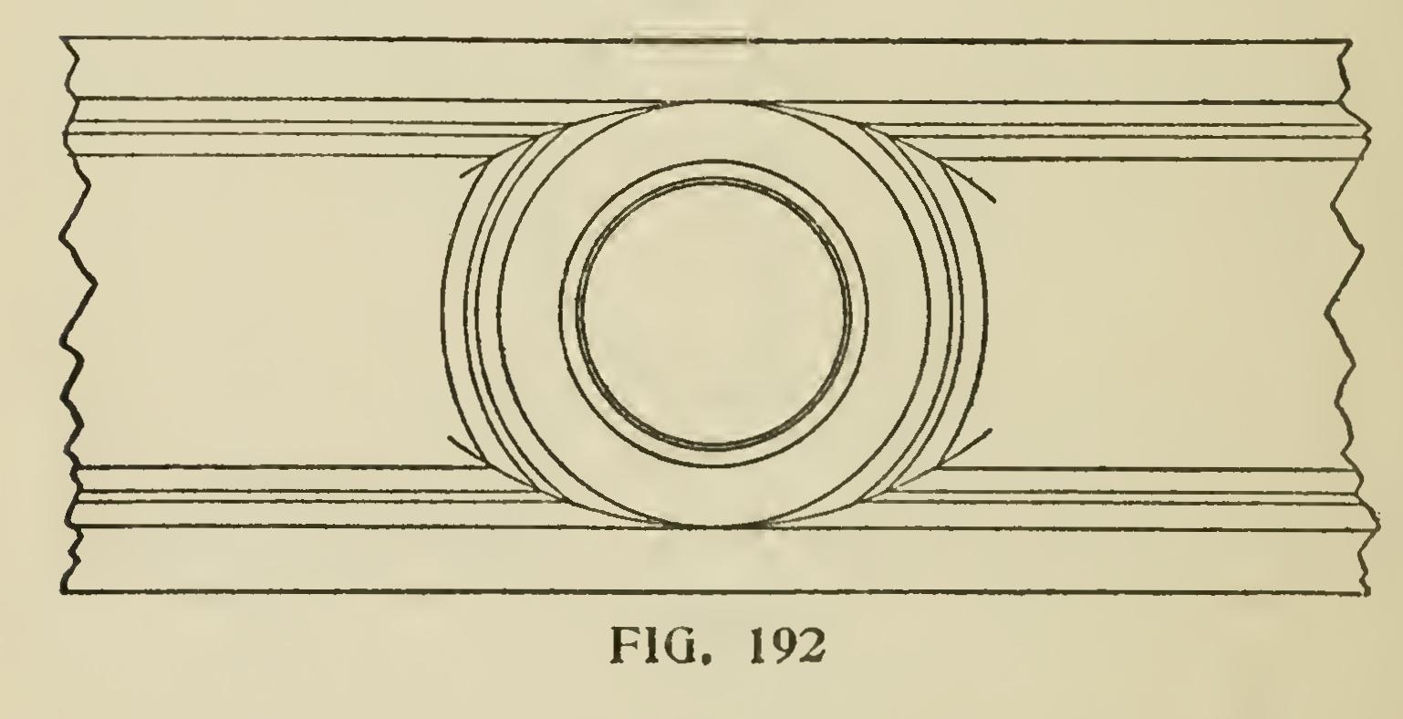
Sometimes the workman will find it necessary to miter in circles between two lines of mouldings, and to do so the circular moulding must be made with a diameter large enough to have the solid wood adjoin the solid wood of the running mould ings, as shown at Fig. 192. It will be seen that the points of juncture of the various members of the mouldings do not run in a straight line, thus making the miter-joint a little curved, which ad mits of the mouldings working together accurately without requiring to be pared.
Figs. 193, 194, 195, and 196 show how various joints are made by the junction of circular mould ings and straight mouldings, and mouldings with more or less curvature.
A spring moulding is one that is made of thin stuff, and is leaned over to make the proper pro jection, as shown at Fig. 197. A shows the spring moulding; B the space left vacant by the leaning of the moulding. These mouldings are difficult to miter, more particularly so when the joint is made with a raking moulding that springs also. Some of the methods given for obtaining the cuts for raking mouldings may be used for cutting these mouldings when the work is straight, but when circular the application of other methods is some times necessary. Many times the workman will come across very knotty operations of this kind to work out, and the following diagrams will then prove exceedingly useful: Fig. 198 exhibits an elevation of a circular moulding mitered into a horizontal moulding. The shape and plan of the moulding is shown at B. It is evident that by producing the line AD to intersect the center line of the arc at C, the central point will be obtained, from which the circular piece required for the moulding may be described. EA and FD give the radius for the curves of both edges when the stuff is in position, as shown in the elevation.
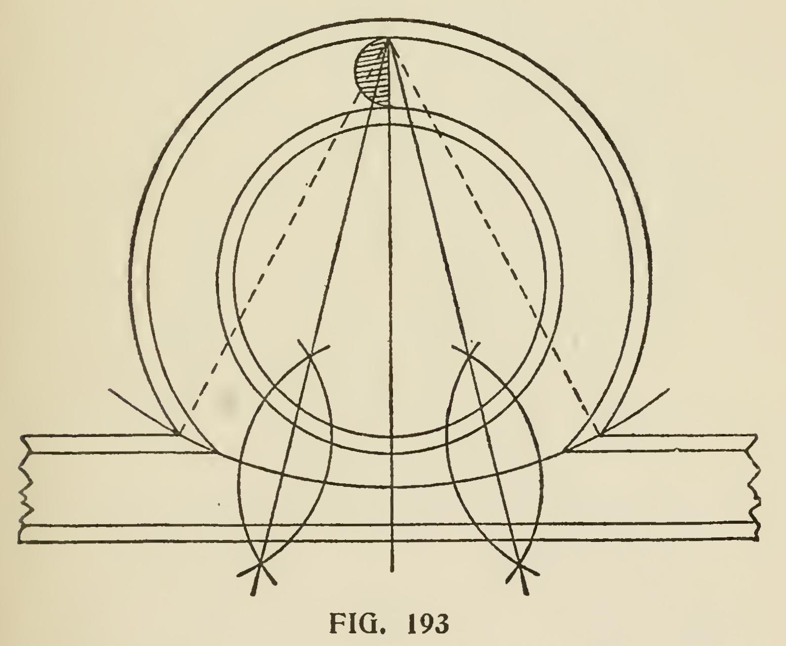
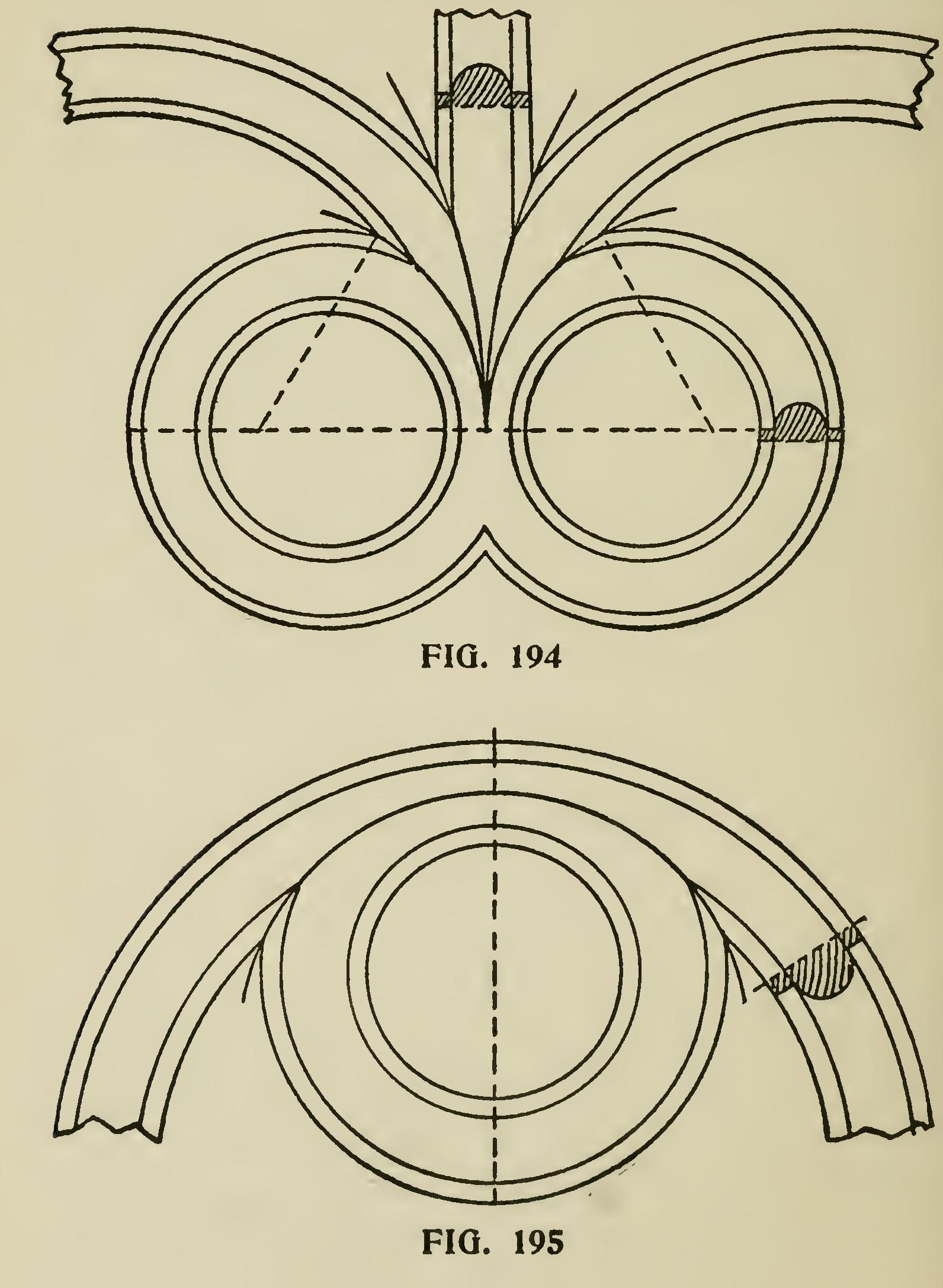
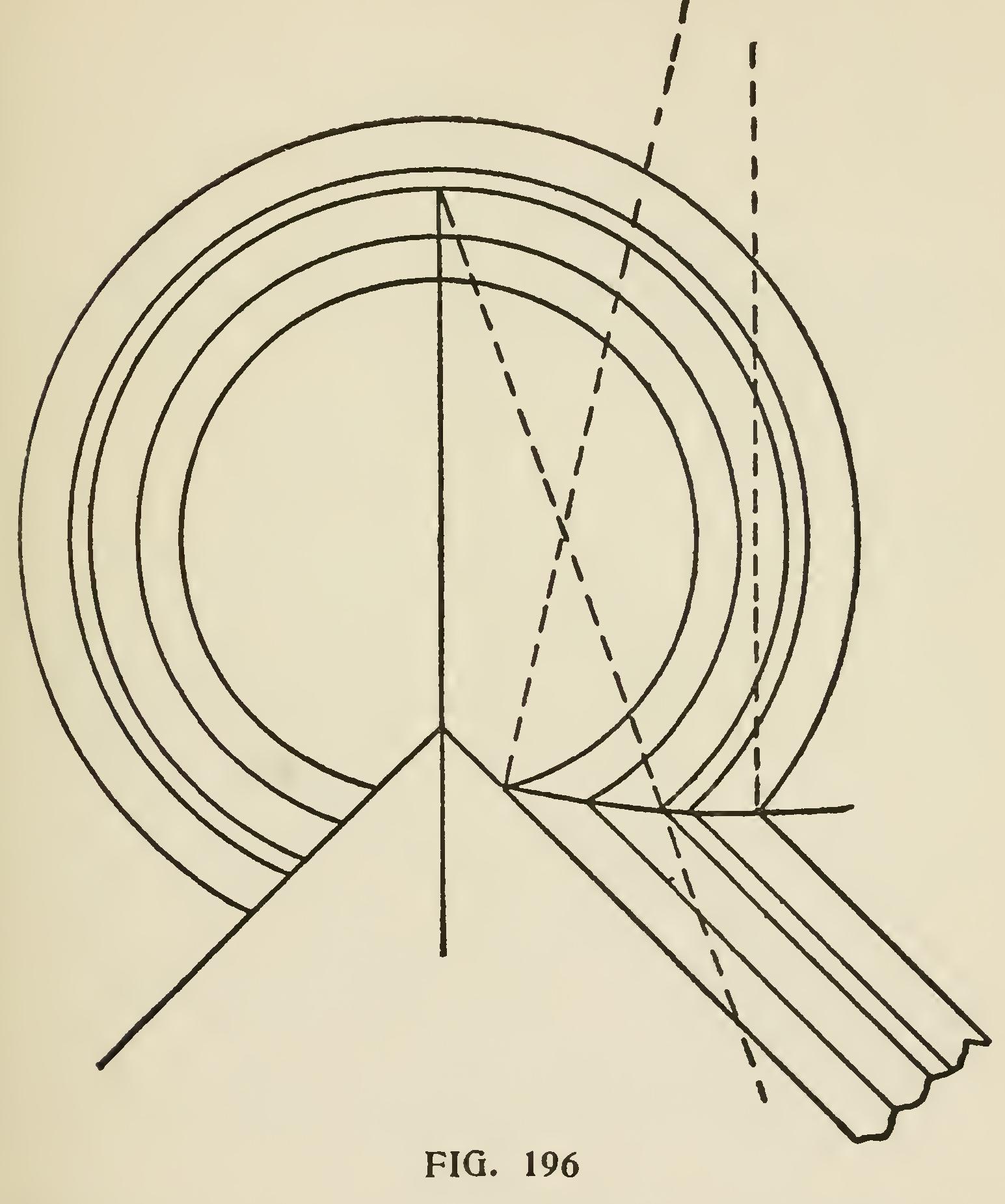
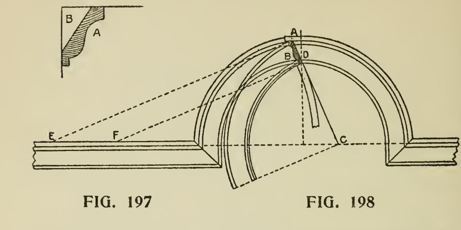
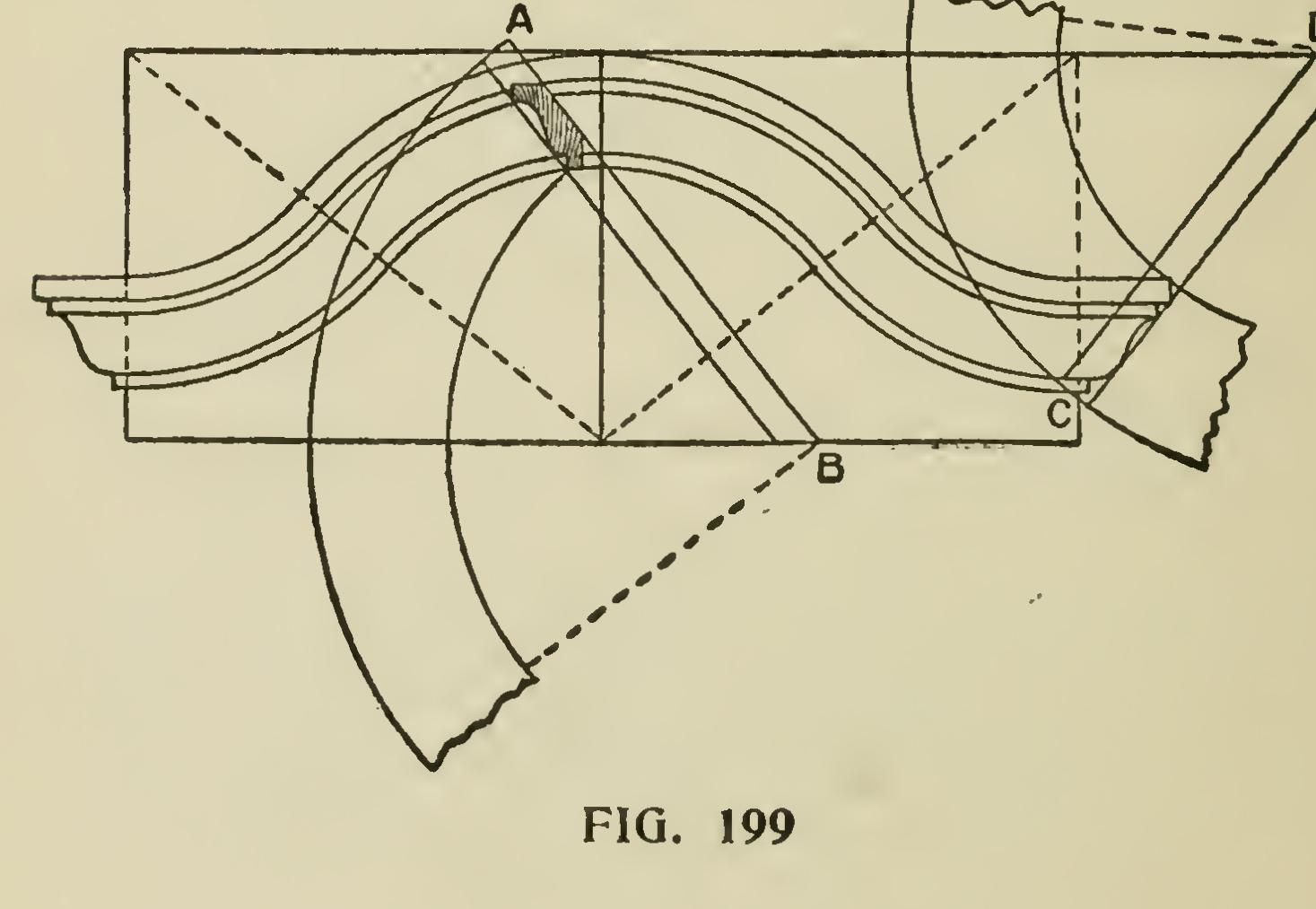
Fig. 199 shows the application of the same rules to a circular elevation of a different form standing over a straight plan. The back lines of the moulding are produced until they bisect a hori zontal line drawn through the center, from which the circular cornice was struck, as shown by the lines AB and CD.