Stair Building
string, tread, riser, risers, treads, line, nosing, shown and edge
Fig. 243 shows the customary way of putting risers and treads together. T, T shows the treads ; R,R the risers ; S,S the string ; 0,0 the cove mould ing under the nosing X,X. B,B shows the blocks that hold the tread and risers together. These blocks should be from four to six inches long, and made of dry wood. Their section may be from one to two inches square. On a tread three feet long, three of these blocks should be used at about equal distances apart, putting the two outside ones about six inches from the strings. They are glued in the angle. It will be noticed that the riser has a lip on the upper edge which enters into a groove in the tread. This lip is generally about inches long, and may be or an inch in thickness. Care must be taken in getting out the risers, that they are not made too narrow, as allowance must be made for the lip. If the riser is a little too wide, it will do no harm, as the overwidth may hang down below the tread ; but it must be made the exact width where it rests on the string. The treads must be made the exact width required before they are grooved or the nosing worked on the outer edge. The lip or tongue on the riser should fit snug in the groove and bottom. By following these last instructions, and seeing that the blocks are well glued in, a good solid job will be the result.

Fig. 244 represents a housed or close string. In this the risers and treads are let into the strings from the back side. Gauge lightly a line from the upper edge of the string, the distance intended to stand above the treads as shown in the dotted line. On this line apply the pitch-board as ex plained on previous pages. In laying out housed strings it is as well to take the fence off the pitch board, as it can be handled much better without it, as the long side will have to be kept close to the gauge line, to insure good work. The top lines for treads and the face lines for risers, are the lines that define the step, and cannot be changed but the back line of the riser and the lower line of the tread should be made to run so that the housing or groove will be wider at the under side of the string than at the junction of the riser and tread at the nosing, where the grooves will be the same width as the riser and tread are in thickness separ ately. The nosing projects over the riser, as will be seen, and to mark this portion out it is usual to make a template or pattern for the purpose. Indeed it is best to make a template to lay out the whole housing of the tread, and in shape as the shaded part is shown in the illustration.
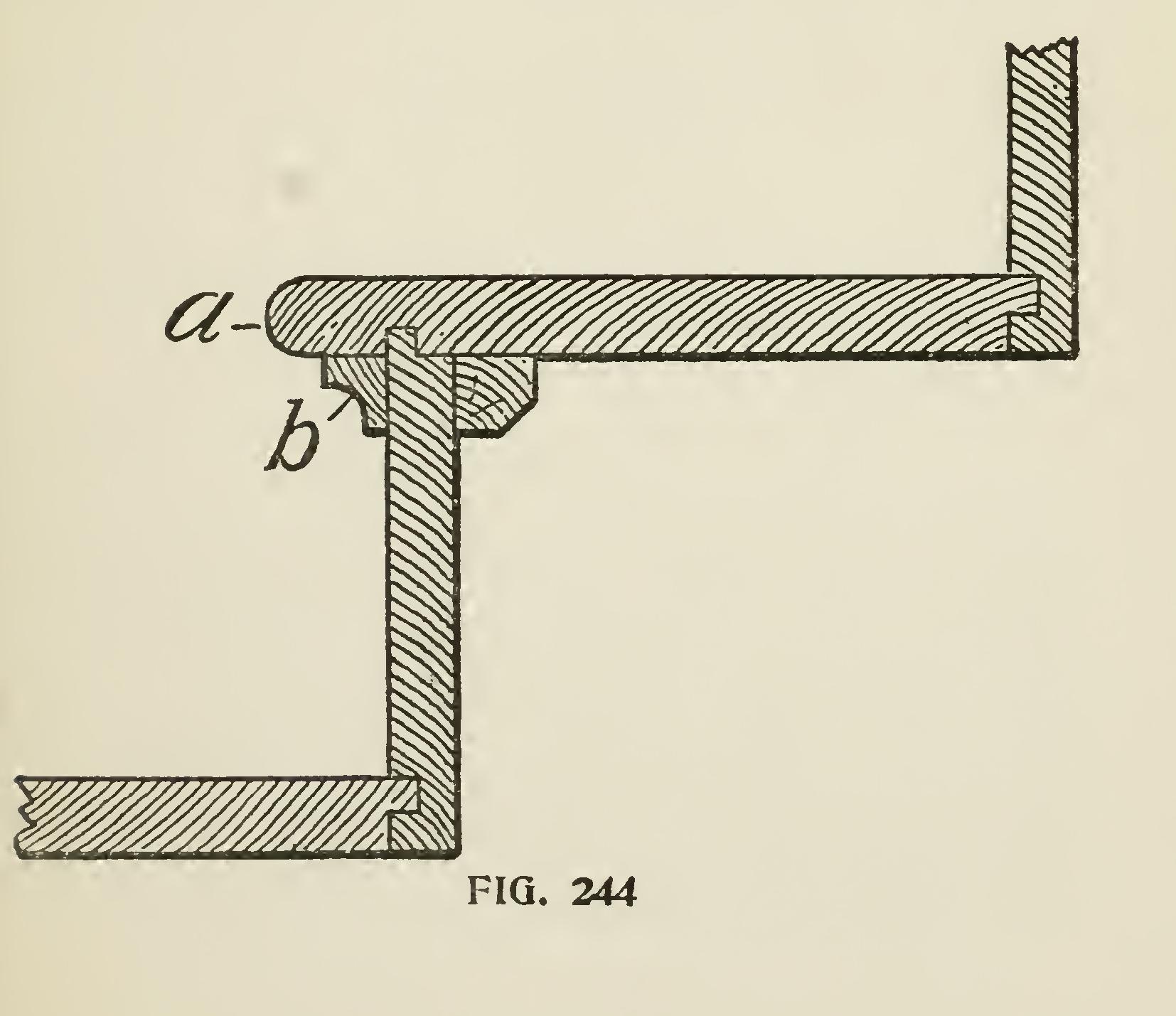
The reason the grooves are left wider at the back edge of tread is so that the wedge can be driven between the tread and the lower edge of the groove, to force the top side of the tread close to the upper edge of the groove, thus making a tight joint and insuring strength and rigidity to the whole struc ture. The risers are also wedged into place as will be shown later on. After the treads and
risers are laid out on the string, a sharp pointed knife blade should be used to mark the lines for the face of the riser and top of tread, then a fine tenon saw should be used to saw down to the exact depth. This will not be difficult to perform when the hole forming the nosing recess has been bored to the proper depth. A gauge line should be made on the back edge of the string to indicate the depth of the housing. Care should be taken in removing the wood from the grooves that too much is not taken or the grooves made too deep. A gauge for trying the depth may be made out of a piece of hard wood, say about four inches long and three inches wide, by about one-half inch in thickness. Make a tenon on the center of one end, about three-quar ters of an inch in width, and cut the shoulders back sufficiently far enough to admit the tenon being long enough to touch the bottom of the groove or housing, when the shoulders rest on the face of the string.
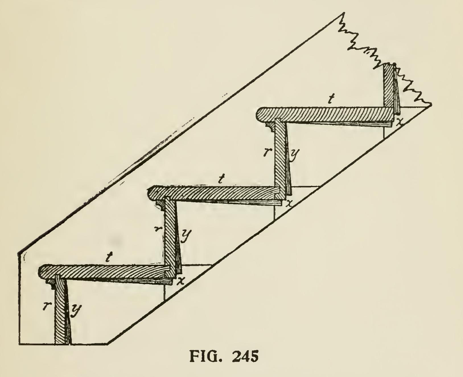
In Fig. 245 we show a sectional elevation through the steps. The treads, t,t, and the risers, r,r, are shown in position. These are secured as will be seen by means of the wedges, x,x, and y,y, which are well covered with glue before they are inserted and driven home. Stairs made after this manner are strong and perfectly solid under foot.
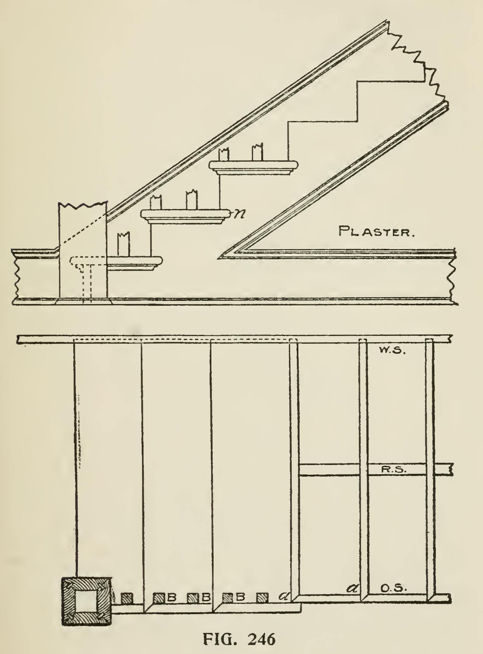
Fig. 246 gives two views of a portion of a better class stair, a stair with cut and mitered string, or open string stair. In referring to the plan, WS shows the wall string; RS the rough string placed there to give the structure strength; and OS the outer or cut string. At a,a, the ends of the risers are shown, and it will be noticed that they are mitered against the vertical or riser line of the string, thus preventing the end wood of the riser from being seen. The other end of the riser is in the housing in the wall string. The outer end of the tread is also mitered at the nosing and a piece of stuff made or worked like the nosing is mitered against, or returned at the end of the tread. The end of this returned piece is again returned on itself back to the string, as shown in the upper portion of the cut, at n. The moulding, which is a five-eighths cove in this case, is also returned round the string and into itself.
The mortises shown at the black points, B,B,B, etc., are for the balusters. it is always the proper thing to saw the ends of the tread ready for the balusters before they are attached to the string, then when the time arrives to put up the rail, the back end of the mortise may be cut out, when the tread will be ready to receive the baluster. The mortise is dovetailed, and, of course, the tenon in the baluster must be made to suit. The tread is finished on the bench, and the return nosing is fitted to it and tacked on so that it may be taken off to insert the balusters when the rail is being put into position.