Framing for Roof Dormers
valley, line, square, common, fig, valleys and shown
FRAMING FOR ROOF DORMERS. Fig. 59 repre sents the plan and the corresponding elevation of the valleys in a roof dormer or gable. For ex ample, 14 feet is taken for the run of the main roof, and 8 feet for that of the gable. The roof of the main part and that of the gable being of the same pitch, it is evident that the ridge of the latter will be below that of the former, as the rise is proportional to the difference in the runs.
A-B
represents the run of the long valley and A' D that of the short valley. Thus it will be seen that valleys framed in this way are self Fig. 59. Framing for Roof Dormers.
supporting. That part from D to B is what is generally termed blind valley, because it is con cealed in the plane of the main roof. The meas urement should be taken along the center of the back of the valley, as shown by the dotted lines; and if backed—or, more properly speaking, grooved, so that the roof boards will have a solid bearing at all points—then the seat cut should be made so as to bring the grooves in the plane with that of the back of the common rafters. This furnishes a problem in itself that is not so Fig. 60. Intersection of Valleys—Roof Dormers.

easily understood as may appear at first sight, especially where there is a projection of the rafter to form the cornice.
However, it is not usual to groove the val leys, as they are generally concealed from view and otherwise not of enough advantage to war rant the extra work required. Where they are not grooved, they should set proportionately lower than the common rafter, so that the under edge of the roof boards will intersect the center of the back of the valley. Even then, that part from D to B would have to be backed or beveled on one side the same as for a hip, to bring the center in plane with the common rafter.
Fig. 60 shows the plan of the valleys at the intersection on a larger scale. In this the sec tions are shown grooved below the intersection; and in that case that part called the blind val ley should be beveled one way, as shown. This part, while it may look out of place in the illus tration, will be found to conform with the roof planes when set in position. In large or heavy roofs, the valleys should be doubled; and in that case it is an easy matter to groove the backs by simply backing them one way only, and then spiking them together so as to form the groove.
In other words, they would show the same as in the illustration by letting the center line repre sent the joining of the two pieces.
Another point comes up in this connection that should not be overlooked before passing on, and that is the joining of the short valley to the long one. Simple as it is, builders sometimes do not readily grasp that it is nothing more than the plumb cut for the valley. It rests at right angles from the long valley, and therefore must rest square against it, just the same as if against a level piece; and in this example, the pitch being 17 and 9 will give the cut.
Referring to the elevation part of Fig. 59, the valleys are shown in position in the roof. They also show the same as the common rafters in their true position; but the valleys resting at an angle of 45 degrees from the common rafter, their lengths per scale are not easily arrived at without a few extra lines, which may be obtained as shown by the dotted lines from the plan to the elevation, as follows: A-E represents the long valley in position from the point of sight, while A-E' shows its length. The same is true of the short valley. It is the same as A-F on the long valley. On a straight view, it represents the length of the common rafter for the gable, but its (the valley) length is found at A-F'.
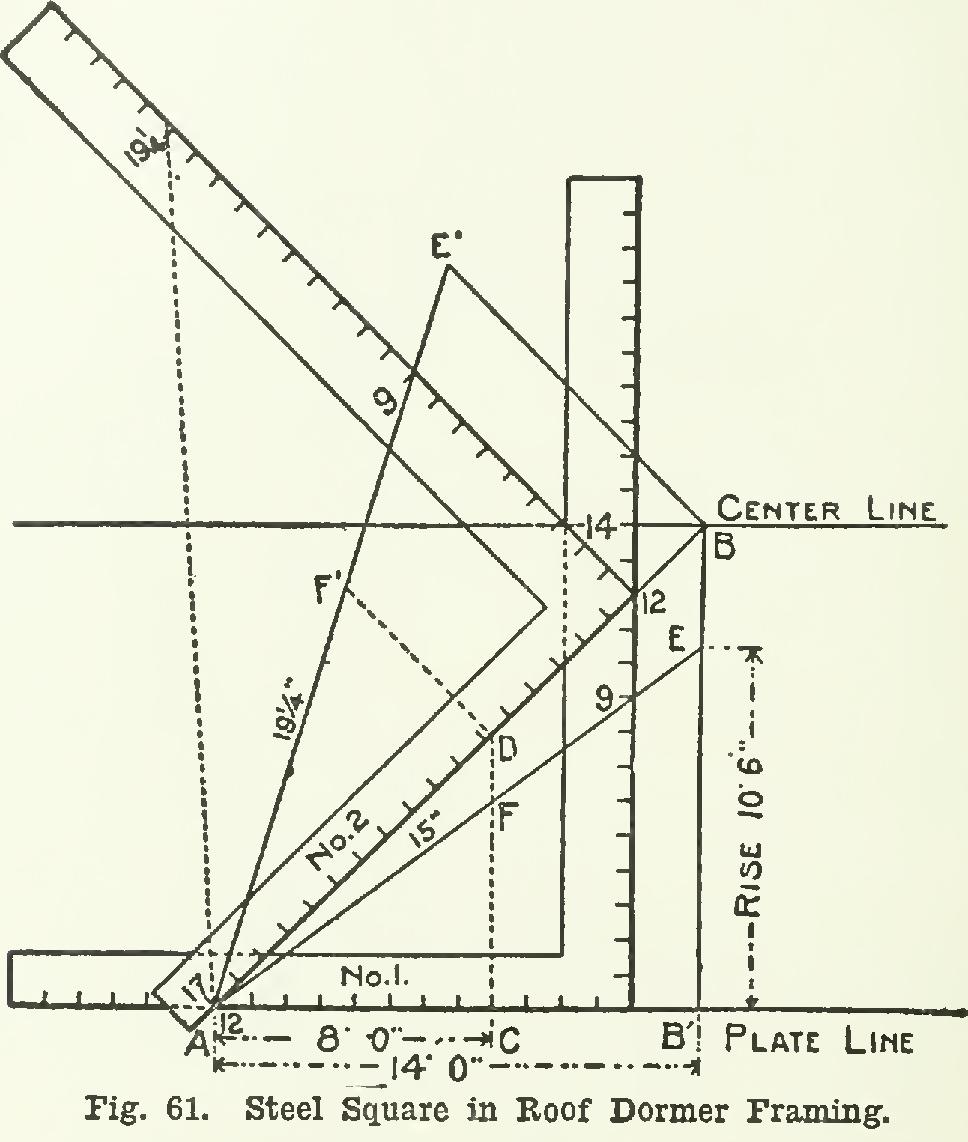
Now we shall illustrate the above by simple lines on the steel square (see Fig. 61), using the same reference letters for the different parts, as shown in Fig. 59. The pitch being or 9-inch rise to the foot, we let 12 on the tongue of square No. 1 represent the starting point, and 9 on the blade the rise. The run of the main roof being 14 feet, measure back 14 inches along the line of the tongue and draw a line parallel to the blade to opposite 14 inches on that member, as at B' B. The line from A to B will represent the run of the long valley. Now, by placing 17 on the tongue of square No. 2 at 12 on the square No. 1, and with the tongue along the line A-B, the heel will rest at 12 on square No. 1. Since the rise is 9 inches to the foot, a line from A passing at 9 on the square No. 2 and intersecting the line B-E' (the rise of the main roof) will represent the long valley; and the line passing at 9 on square No. 1, inter secting the line B' B as at E, will represent the common rafter for the main part.