Tile Veneer for Frame Buildings
arch, arches, bricks, fig, brick, joints, lintel, flat and relieving
Fig. 110 shows two relieving arches, one being laid out in the wrong way, and the other correctly. The first is wrong because, in the case of fire, the wooden lintel would be con sumed, and the thrust of the arch on the burnt end would be bound to cause a failure and endanger the whole of the wall above. A better way is shown. Instead of making the span of the relieving arch equal to the opening between the jambs below, the arch springs from a point over the extreme end of the wooden lintel. In case of fire occurring and the lintel being entirely consumed, the arch would be unaffected, and would continue to carry the weight above.
Building inspectors and managers should insist on the adoption of this correct method, for it costs no more than the incorrect one, and the advantage of it in case of fire is greatly in its favor.
Of course, for such arches, no elaborate cen tering is necessary. The lintel is laid in posi tion; and a piece of stuff is shaped to the ,curve of the arch, and laid upon the lintel to form the centering. The arch is then turned upon this centering, which is removed when the mortar is properly set, the core being then filled in with brickwork.

For openings up to three feet or thereabouts, a relieving arch of a single ring of half-bricks is all that is required; but for larger openings, several rings may be used.
Fig. 111 shows an arch of three rings, and it will be noticed that each arch is separate and not bonded into its fellows. It will also be noticed that the bricks of these rough reliev ing arches are not cut taper, and thus the joints are slightly more open on the back of the arch than on the under side. In making drawings of such arches, the draftsman draws a ring around the center from which the arch is struck, Fig. 111. Segmental Arch, and How to Lay It Out.
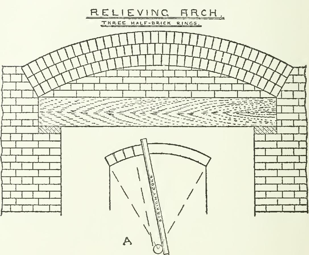
the diameter of the ring being the thickness of the brick. This thickness is then stepped off on the under side (soffit) of the arch with a pair of dividers, and the straight edge placed against the ring and one of the divisions on the soffit (see A, Fig. 111).
How to Lay Out Arches. The chief prob lems, however, with which the practical layer out of arches is confronted, arise in connection with the modern use of fine pressed brick for so many first-class structures. For while the mere curve is sufficient for practical purposes in rough relieving arches, the arch made of facing bricks, and forming a feature of some fine front, must be set out exactly for the purpose of cut ting and fitting, or perhaps moulding, the bricks of it is to be composed. Brick arches in which the bricks have been specially cut or moulded are generally termed gauged arches, and are frequently used nowadays.
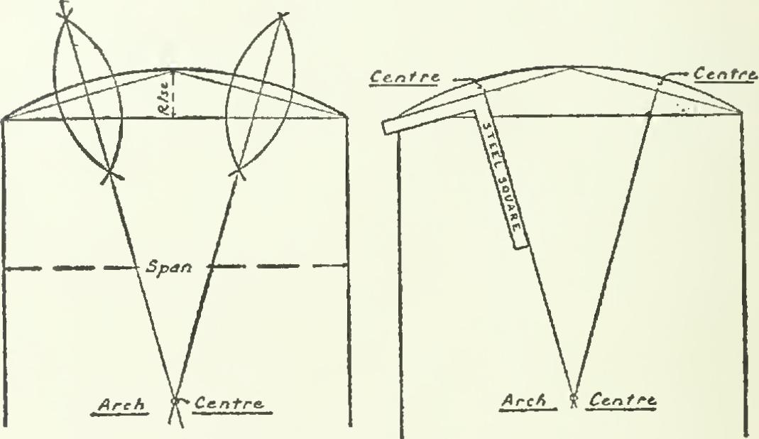
The radius of the arch is scarcely ever given by the architect, the rise being almost invari ably denoted instead. The writer has before him an elevation of a brick-fronted building with some eight or ten openings of varying widths, but the same rise is specified for all the arches over them. This means that the
layer-out has to find the centers of the several curves from the given particulars of their rise and span. This he does as shown in Fig. 112, the first being the geometrical method of the drafting room; the second, the practical method of the laying-out shop. In both cases, the center from which the arch is struck is found at the intersection of the lines drawn from the center of each half of the arch.
As the bricks in gauged arches are used full length, the thickness of the brick is marked off around the back of the arch, and the joints drawn to the center, as in Fig. 113, at left. The joints are very fine, being usually specified to be not more than inch, the mortar being either fine cement or lime putty.
In Europe, special bricks are made for such arches, and are known as red rubbers. When new, they are quite soft, and can be sawed with a handsaw, and rubbed upon a block with sand and water to form close joints. After being Fig. 112. To Find the Arch Centers.
exposed to the air for a time, the surface of these bricks becomes exceedingly hard and imper vious to the action of the weather. For the red brick dwellings of "Queen Anne" and "Colonial" style, now so much in vogue again, such bricks are exceedingly useful. Not only can they be cut for the characteristic flat arches of these styles, but mouldings can be worked on the angles, and panels formed to relieve broad surfaces of wall. More often, however, bricks for gauged arches are specially moulded to the builder's drawings by the makers of the face bricks, with fairly good results in the fin ished work.
The flat arch just referred to is also much used in brick fronts in city buildings, and is drawn as shown in Fig. 113, at right. It pre sents no difficulty to the layer-out, the joints Fig. 113. Brick Arches.

being found by making a curve above the arch and stepping off the thickness of the bricks upon it.
There is one important point to be remem bered, though, in building such arches—namely, that a perfectly straight soffit will always appear to be sagging. The remedy for this is to allow a trifling rise—say 1A inch for every three feet of span—which will be sufficient to make the under side of a flat arch look straight. This can be easily clone on the job by laying two strips tapering from nothing at the ends to the required allowance at the middle, upon the support or centering on which the mason forms his arch.
Of course, flat arches are not very desirable, from a structural standpoint, and should not be used for spans more than four or five feet at the outside. Occasionally, for the sake of uni formity, a flat arch is used over a larger open ing, perhaps a broad window or doorway; but in such cases the weight of the superstructure is carried on iron girders, and the brick arch is only a sham or casing toward the street.