Testing of Structural Steel 23
inch, elastic, elongation, limit, inches, bar, square and pounds
The rate of increase in inches per amount of load is constant for all lengths, sizes, and classes of steel up to a certain point—namely, where the rate of increase in elongation changes. That is, the elongation, divided by the number of pounds which produce that elongation, gives practically the same result for all steels. This result is 30,000,000, and is called the modu lus of elasticity—that is, the measure of elas ticity. It signifies that the elongation, for each inch in length up to a certain point, is, when measured in inches, equal to one thirty-millionth of the load in pounds per square inch of cross section of the bar. It is expressed in the follow ing manner: in which, .A=Total elongation in inches in a length of 1 inches ; 1=Length over which the elongation is desired; P=Load on the bar; A=Area of the bar in square inches ; and E=30,000,000.
For example, if a bar inch in diameter is 18 feet long, and it is known to carry a stress or load of 18,030 pounds, the total stretch would be: Here the 18 feet is reduced to inches by multi plying by 12, and the 0.6013 is the area of a round rod (C 261).
After the rate of elongation has changed from what it was at the start, the steel has begun to fail. This point occurs when the stress gets to be from 1/2 to of the ultimate, and the point is called the elastic limit. Mark this well, and note that no allowable stresses should ever be above the elastic limit. It is immaterial what the ultimate strength of a material may be; the elastic limit is what the engineer or the designer must know, and he must realize its importance.

If the elongations are measured by delicate instruments (called extensometers), and the readings of the scale beam are taken at the same time, the machine of course being stopped while the readings of the extensometer and the scale beam are being taken; and if the elongations axe plotted or laid out on a diagram from left to right along the horizontal, and the pounds per square inch are plotted along the perpendicular, lines drawn from these points will meet in a series of different points; and a line drawn through these points will give a curve, Fig. 19, which will show the elastic limit and the ultimate strength. Sometimes the machines have instruments attached that draw the curve while the test is going on. Fig. 19 is a curve of an actual test. The total elongation in 8 inches is seen to be 2.1 inches, and the percentage of elongation is therefore 2.1÷8.26.25, which is better than is usually specified. The elastic limit is seen to be 54,500 pounds per square inch, and the ultimate strength is 75,000 pounds per square inch.
These values are too high for structural mate rial, although the test piece was a piece cut from a rod. Evidently the rod got too cool during the last few passes in the rolls, and there fore it was cold-rolled to some extent. This would account for its rise in strength.
Fig. 19 shows that just after the elastic limit is passed the material stretches out very fast, and that the load for a little while is less than it was at the elastic limit. This is called the yield point, and in commercial testing is some times but incorrectly spoken of as the "elastic limit." The yield point may be determined without the use of extensometers, since the beam on the testing machine will drop down for a few seconds. A common operation is the determina tion of the yield point by the drop of the beam.


When the ultimate strength is reached, the bar begins to neck down rapidly at some point, and quickly breaks, sustaining a load just before fracture about equal to the elastic limit. A necking-down point is shown in Fig. 20; and the two pieces just after fracture are shown in Fig. 21. The lower half is shown in section in order to show the cup-shaped fracture more closely. This fracture is characteristic of medium steel.
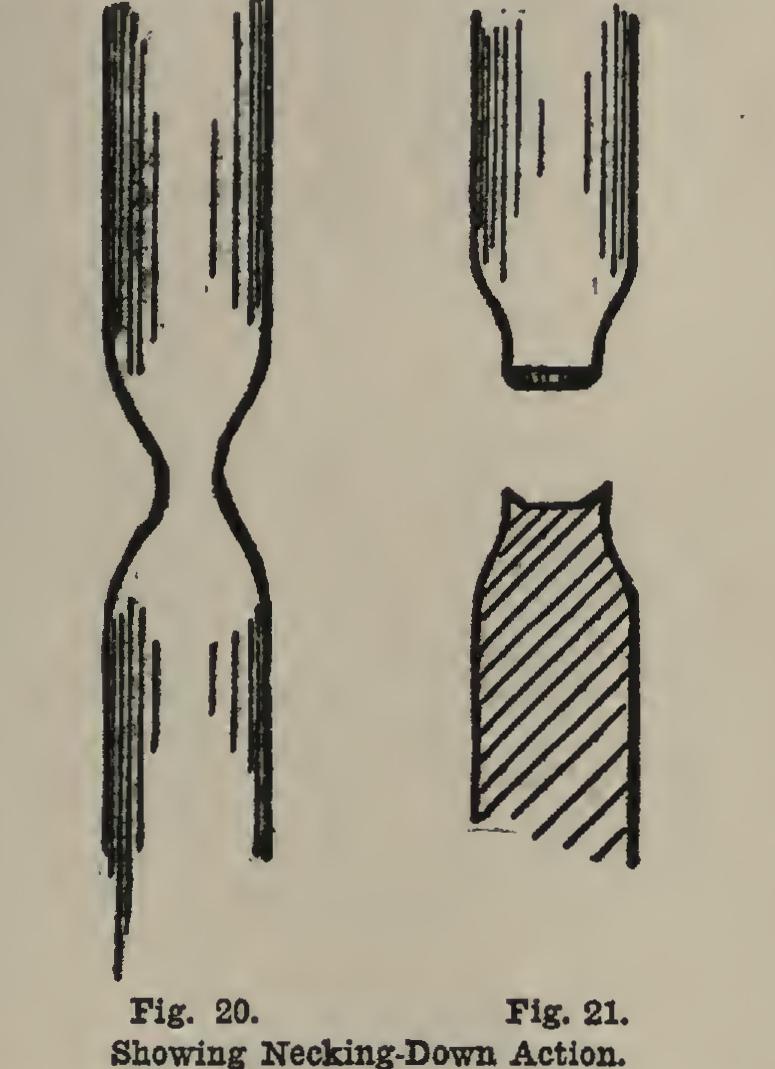
Soft steel does not show it; while hard steel shows little if any necking down, and breaks straight across.
This reducing is called the reduction of area, and is an index of the malleability of the mate rial. The amount of reduction of area is ex pressed as a percentage of the area of the origi nal cross-sectional area. Thus, if the bar was inch = 0.750 inch in diameter before testing, and 0.432 inch in diameter at the fractured part, the following is true: Original area of 0.750-inch bar (C 261)=0.4418 square inch; Area of fractured end of 0.432-inch bar (C 289)=0.1466 square inch; Reduction of area=0.4418-0.1466=0.2952 square inch; Reduction of area in per cent=0.2952÷0.4418=66.8, which is very good for structural steel.
Where the materials are subject to shock, as in case of railroad rails, the material, after it has been formed into the completed article, is subjected to an impact test. This consists in letting a certain weight drop from a certain height and strike the test piece, which is usually a beam, in the center. The amount of deflection is then measured, and the beam is struck an other blow. The deflections under succeeding blows are measured, and the general distortions are observed. From this data can be deduced an idea of the ability of the article to withstand impact, which is another name for the striking of a blow or blows.