Cement Construction Reinforced Concrete
beam, tension, steel, rods, reinforcing, strength and compression
CEMENT CONSTRUCTION REINFORCED CONCRETE Introduction. Reinforced concrete is con crete in which steel has been embedded. to give additional strength and elasticity.
Steel has about the same strength in tension when used as a beam, as it has in compression when used as a column or post. The same thing is approximately true of wood and some other materials of construction. In concrete, however, . the conditions are quite different, the compres sive resistance of concrete being about ten times its tensile resistance.
In a concrete beam, the upper portion of the beam is in compression, and the lower part is in tension. The line where the internal stresses of the beam section change from compression to tension is Called the neutral axis.
The forces must balance on each side of the neutral axis. A plain concrete beam, being so much stronger in compression than in tension, will have its neutral axis located very low.
Steel is so much stronger in tension than con crete that a very small steel rod or bar placed in the bottom of a concrete beam will raise the neutral axis and balance the compressive forces exerted above.
183 Plain concrete, when used in the form of pil lars and posts, is capable of carrying heavy direct loads through its great compressive strength. But when it is subjected to a direct pull—that is, to tensile strains—it is weak. For example, if a plain concrete beam is subjected to a load, it will break apart at the bottom just as a piece of chalk would under like conditions, being unable to resist the tension in the lower portion of the beam. In order to overcome this, reinforcing steel is used to give proper tensile strength and elasticity. The concrete in the top of the beam takes care of the compression. A properly reinforced concrete beam, therefore, has the strength of stone in resisting compres sion, united with the tension-resisting power of steel.
When a beam is loaded and supported at the two ends, it will have a tendency to deflect or bend. To illustrate, assume that a beam is made up of a series of flat plates—or, in other words, like a pad of paper or a book—the difference being that in the pad of paper the leaves are not in any way connected to one another, whereas in a beam the adhesion or sticking together of the various particles of the material ties the imaginary plates together. Now, when the sup posed beam starts to deflect, one of two things will happen: either the various plates separate, as when a book or pad of paper is bent, and, in separating, slide by one another; or, if the plates are held together and sliding is prevented, the particles in the upper plates compress, and those in the lower plates elongate or stretch out.
It is thus seen that in addition to the com pression and tensile stresses in the top and bot tom of the beam, there are internal stresses of equal importance, against which the concrete must also be properly reinforced. These may be tensile or they may be shearing forces.

Fig. 39 shows a plain concrete beam, sup ported freely at the ends, which has failed upon the application of a small load applied near its center.
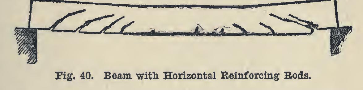
Fig. 40 shows a similar beam having horizon tal reinforcing rods located near the bottom sur face of the beam. The method of failure under a medium load, in this case, was said to be due to the ends of the reinforcing rods slipping in the concrete. The diagonal or slanting cracks are partially due to horizontal shear set up by the bending of the beam. These are sometimes spoken of as due to diagonal tension.
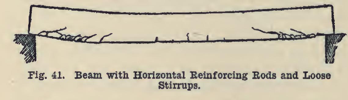
A means of fortifying against horizontal shear is by the use of stirrups. Bands or rods of steel or iron are bent in the shape of a U, and either placed loosely around, fastened rigidly to, or made as a part of the reinforcing rods. The detail of this construction will be given later under the head of "Materials for Reinforce ment" and "Reinforcing Systems." Fig. 41. shows the method of failure of the same type of beam as previously shown, but having loose stirrups surrounding the horizontal reinforcement bars and embedded vertically in the concrete. This beam failed when tested to destruction, by the slipping of the horizontal rods. The figure shows the shearing of the con crete along the horizontal plane above the rods, but no diagonal cracks. The stirrups evidently prevented the shearing action above the rods. As a means of preventing such a method of fail ure, some companies have either rigidly fixed the stirrups to their reinforcing bars or formed them as a part of same. The result of such a construction seems to throw the greater part of the body stresses of the beam onto the hori zontal bars for support. Some authorities con sider this a weakness in the construction.