Reinforced Concrete Columns
column, tile, steel, shown, lower and fig
REINFORCED CONCRETE COLUMNS A reference to the figures shown in the pages devoted to the different systems of reinforce ment will show the general types of columns used in reinforced concrete work.
The general plan of all reinforced columns seems to be that of a cage supported by upright members and filled with concrete, the outside being likewise protected from fire and corrosion by a thick layer of concrete. This cage may be made up in various ways. Two of the common ways are as follows: (a.) By the use of some form of coil of metal sur rounding the vertical bars ; (b) By the use of tie-rods spaced regularly up the length of the column.
A few additional details will now be shown, that were not shown in the previous figures.

Fig. 108 represents the "Smith" form of col umn hooping. A special vertical reinforcing bar is used with this hooping, and is shown in detail. The reinforcement consists of a continuous spiral of cold-drawn wire of high elastic limit, rigidly held in place and alignment by clinching into the bar.
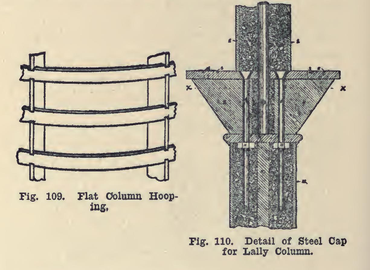
Fig. 109 shows the Kahn form of flat bar col umn hooping. The hooping material is inch by 1/4 inch, and can be procured in coils of any diameter. The spacing bars are inch by inches, and are punched to receive the coil. The hooping is wedged into place and held rigidly by compressing the spacing bars.
Fig. 110 shows a novel form of column con struction, known as the Lally column. These columns are factory-made by special machinery which, it is claimed, eliminates all air-holes or cavities. The outside shell is of steel; the filling is of sand, cement, and blue trap-rock, with an inner core of steel. The details shown in the figure are as follows: 1—Represents steel shell of upper column.
2—Represents crown-plate of bracket-cap upon which beams or girders rest.
3—Holes for bolts to fasten beam to plate 2.
4, 5—Represent tie-bolts passing from crown-plate 2, through brackets 8 and 9, also through cap 7, entering the casing 11 of the lower column, and also embedded in the concrete.
6—Represents a steel rod or pintle embedded in the concrete at the base of the upper column, extending into the cap of the lower column, resting on cap-plate No. 7; thus holding the upper column firmly in position.
7—Represents a cap-plate which sets on casing No. 11 of the lower column, forming a seat for brackets 8 and 9, through which the bolts 4 and 5 pass.
8, 9—Are brackets setting on cap 7, extending to the under side of crown-plate 2, with bolts 4 and 5 passing through same, making a bracing support for crown-plate 2, on which beams rest.
10—Represents a reinforcement of steel embedded in concrete of lower column, passing from under side of cap 7 to base of column.
11—Represents steel shell of lower column.
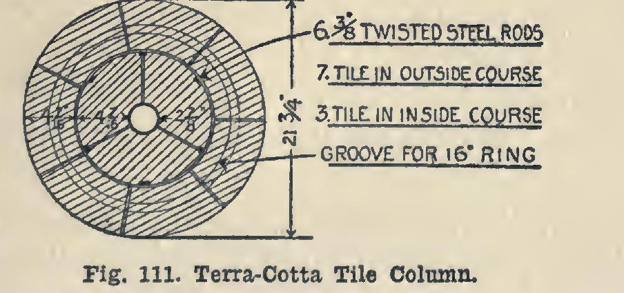
Fig. 111 shows a form of terra-cotta tile col umn. The column whose cross-section is shown was built of special-shaped, hard-burned, terra cotta tile, laid with Portland cement mortar joints, and is reinforced by six twisted steel rods. The special-shaped tile con sisted of two concentric rings, the inner one be ing composed of three tile and the outer one of seven tile. The reinforcing rods are in the joints between the inner and outer rings. This particular column was inches in diameter, and 21 feet inches high. Through its cen ter, there is a diameter opening. In the outside layer of tile there is a 1-inch groove, inch deep; and in this groove on each course of tile, there is placed a ring, 16 inches in diameter, of wire.
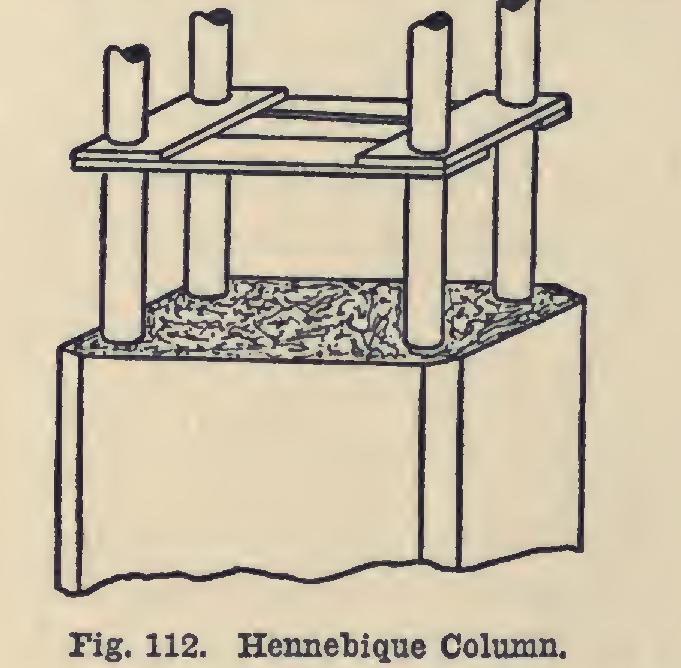
Fig. 112 shows a form of Hennebique column.
Plate 19 shows the type of reinforcement used in the columns of the Turner Mushroom System. This column was used in a stock-house for the Hamm Brewing Company of St. Paul, and was designed to carry a 1,000-ton load. The finished column was a 30-inch octagon 26 feet high.